Torsion spring for MEMS structure

Active Publication Date: 2005-07-26
SAMSUNG ELECTRONICS CO LTD
View PDF3 Cites 13 Cited by
  • Summary
  • Abstract
  • Description
  • Claims
  • Application Information

AI Technical Summary

Benefits of technology

[0013]Preferably, a distance between the plurality of connection bars is equal to, or greater than a width of one of the plurality of beams. By controlling the distance, a ratio of bending stiffness to torsional stiffness may become greater. A

Problems solved by technology

However, in a MEMS structure, the manufacturing process may be very complex or require several additional processes to manufacture a torsion spring having a circular section or a cross-shaped section as described above.
For example, as the length of the beam increases, both the bending stiffness and the torsional stiffness become weaker.
Therefore,

Method used


Image

  • Torsion spring for MEMS structure
  • Torsion spring for MEMS structure
  • Torsion spring for MEMS structure

Examples


Example

[0023]Korean Patent Application No. 2002-07052, filed Feb. 7, 2002, and entitled: “Torsion Spring for MEMS Structure,” is incorporated by reference herein in its entirety.

[0024]The present invention will be described more fully hereinafter with reference to the accompanying drawings, in which preferred embodiments of the invention are shown. The invention may, however, be embodied in different forms and should not be construed as limited to the embodiments set forth herein. Rather, these embodiments are provided so that this disclosure will be thorough and complete, and will fully convey the concept of the invention to those skilled in the art. Like numbers refer to like elements throughout.

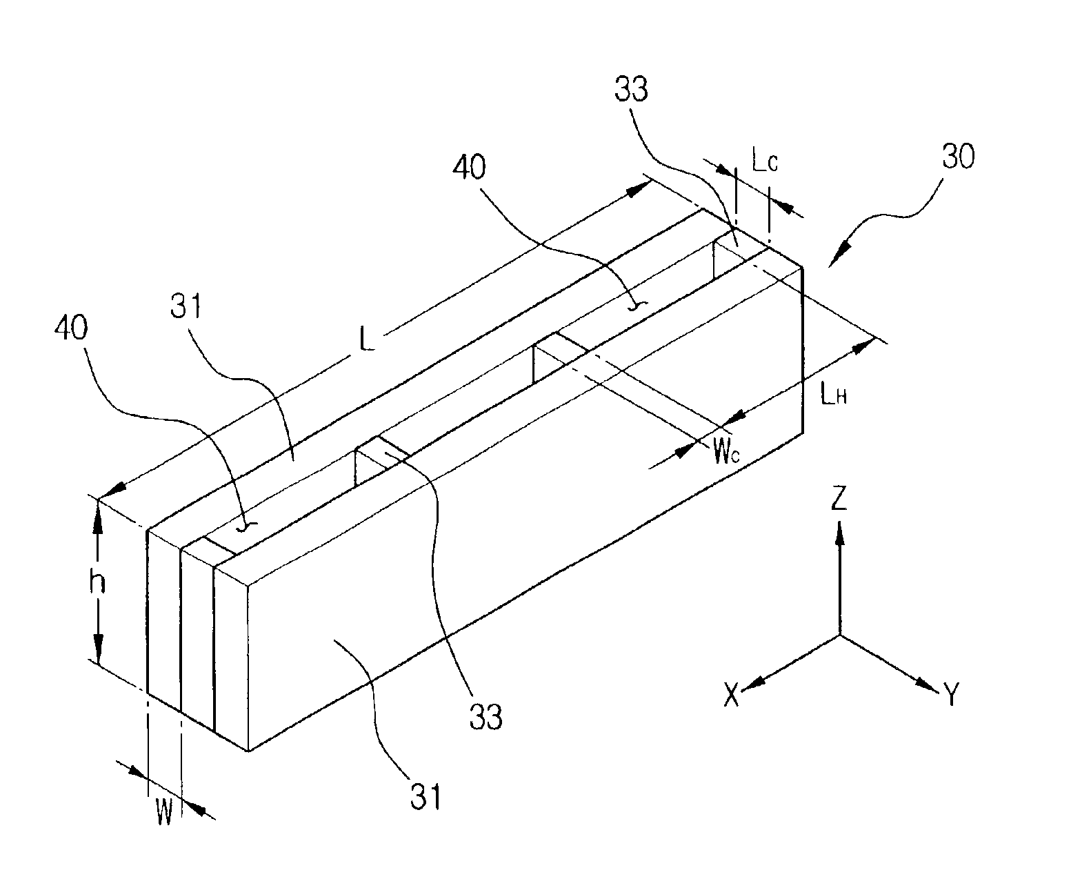
[0025]FIG. 3 illustrates a perspective view of a torsion spring for a MEMS structure according to an embodiment of the present invention. The torsion spring 30 according to the present invention includes a pair of beams 31 and four connection bars 33 to connect the beams 31. A torsion spring acco...


PUM


Abstract

A torsion spring for a MEMS structure has a plurality of beams, each beam having two ends wherein both ends are fixed to a predetermined area, and at least one connection bar disposed at a right angle to a lengthwise direction of the plurality of beams, wherein the at least one connection bar connects the plurality of beams. Preferably, the distance between the connection bars is equal to or greater than the width of one of the plurality of beams. Accordingly, a torsion spring according to the present invention has a bending stiffness greater than a torsional stiffness, which allows easier torsion. Further, a torsion spring according to the present invention may be easily fabricated by etching.

Description

BACKGROUND OF THE INVENTION[0001]1. Field of the Invention[0002]The present invention relates to a torsion spring for a micro electro mechanical system (MEMS) structure. More particularly, the present invention relates to a torsion spring having a greater bending stiffness than a torsional stiffness.[0003]2. Description of the Prior Art[0004]Micro electro mechanical system (MEMS) technology is used in the manufacture of mechanical and electric elements through semiconductor processes. MEMS technology usually includes a structure mounted on a substrate and other parts, such as a spring, to support the structure and allow the structure to move in a predetermined direction. For example, to manufacture a MEMS gyroscope, there should be a mass mounted on a substrate and a torsion spring formed on the substrate in order to support the mass, which is to be rotated around a particular axis.[0005]In the above MEMS structure, the torsion spring should allow the structure to be rotated in a ce...

Claims


Application Information

Patent Timeline
IPC IPC(8): B81B3/00G01C19/56F16F1/14
CPCB81B3/007B81B2203/0118B81B3/00
Inventor JEONG, HEE-MOON
Owner SAMSUNG ELECTRONICS CO LTD
Why Eureka
Try Eureka