Kinematic optical mounting assembly with flexures

a technology of mounting assembly and kinematics, applied in the direction of mounting, optics, instruments, etc., can solve the problems of affecting the exposure process, affecting the effect of the mounting assembly, and releasing gas that could harm the environment of the cell assembly

Inactive Publication Date: 2005-07-26
NIKON CORP
View PDF18 Cites 29 Cited by
  • Summary
  • Abstract
  • Description
  • Claims
  • Application Information

AI Technical Summary

Problems solved by technology

The attachment techniques used to secure optical elements in conventional cells pose several problems.
In a photolithography system where an inert gas, such as nitrogen or helium, is introduced inside the optical barrel surrounding the cell assembly, the adhesive may release gas which could be harmful to the environment of the cell assembly.
For example, the gas released from the adhesive may absorb the exposure light and hamper the exposure process.
One problem with conventional cells utilizing friction clamping is that the clamping force retains or pinches the optical element, which often causes the surface of the optical element to deform.
Moreover, when the optical barrel is severely disturbed, such as when it is being shipped from the manufacturer's site to a production site, the clamping force may cause the optical element to break.

Method used


Image

  • Kinematic optical mounting assembly with flexures
  • Kinematic optical mounting assembly with flexures
  • Kinematic optical mounting assembly with flexures

Examples


Embodiment Construction

[0030]Reference will now be made in detail to several exemplary embodiments of the invention that are illustrated in the accompanying drawings. Wherever possible, the same reference numbers will be used throughout the drawings to refer to the same or like parts.

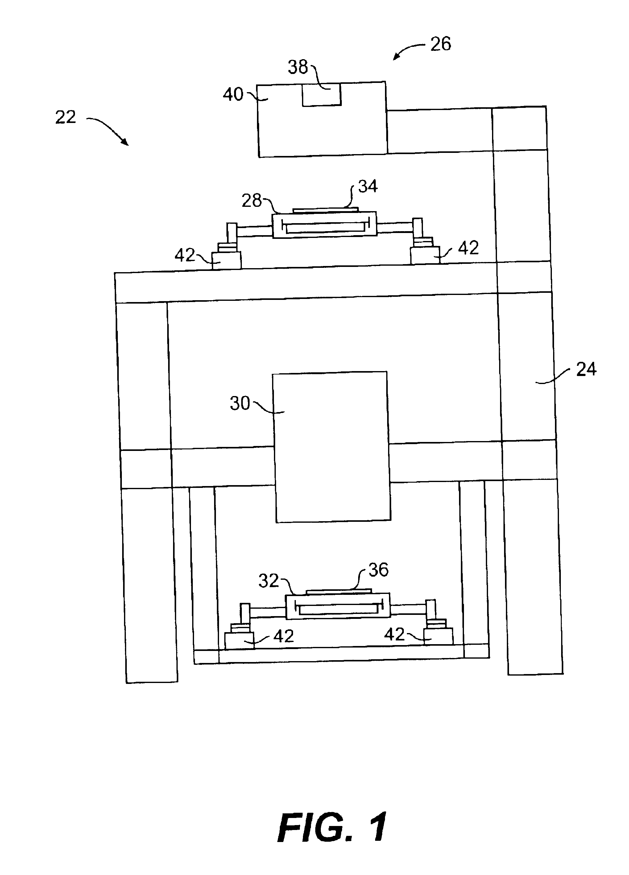
[0031]The kinematic optical mounting assembly of the present invention will be described with reference to a photolithography device 22 shown in FIG. 1. As shown, photolithography device 22 includes an apparatus frame 24 supporting the components of the system, including an illumination system 26, a reticle stage 28, an optical barrel 30, and a wafer stage 32. Apparatus frame 24 is rigid and mounts to a base, such as the floor or another supporting structure. The design of apparatus frame 24 may vary to suit the design requirements for the rest of photolithography device 22. For example, separate individual structures (not shown) may be used to support the components of the system.

[0032]In operation, photolithography device 2...


PUM


Abstract

A kinematic optical mounting assembly secures an optical element to a base. A plurality of first bracket assemblies and second bracket assemblies are secured to the base and engage the optical element. Each first bracket assembly constrains the optical element from movement relative to the base in a direction substantially parallel to an axis of the base. Each second bracket assembly constrains the optical element from movement relative to the base in a direction substantially perpendicular to the axis of the base and substantially tangential to a periphery of the base. Six independent bracket assemblies constrain the optical element in six degrees of freedom to provide kinematic constraint without bending moments.

Description

[0001]This application claims benefit of priority of U.S. Provisional Patent Application No. 60 / 392,936, filed Jul. 2, 2002.BACKGROUND OF THE INVENTION[0002]1. Field of the Invention[0003]The present invention relates to a mounting assembly for supporting an optical element and, more particularly, to a kinematic optical mounting assembly with flexures for supporting an optical element, such as a lens or a mirror, in a cell body.[0004]2. Description of the Related Art[0005]Conventional devices for manufacturing integrated circuits utilize a photolithographic process to reproduce a circuit pattern from a reticle (e.g., photomask) onto the surface of a wafer. In this process, radiant energy is transmitted through non-opaque portions of the reticle, through a projection exposure apparatus, and onto a surface of the wafer coated with photosensitized silicon or other semiconductor material. Conventional devices use visible and ultraviolet light as a radiant energy source. The portions of ...

Claims


Application Information

Patent Timeline
Patent Type & Authority Patents(United States)
IPC IPC(8): G02B7/02
CPCG02B7/023
Inventor WATSON, DOUGLAS C.PHILLIPS, ALTON H.HATASAWA, MASATO
Owner NIKON CORP
Why Eureka
Try Eureka