
Blood flow gated MRI

a technology of magnetic resonance imaging and gated mri, applied in the field of magnetic resonance imaging arts, can solve the problems of affecting the spatial encoding, collecting data, and affecting the image quality,

Inactive Publication Date: 2005-07-26
KONINKLIJKE PHILIPS ELECTRONICS NV
View PDF6 Cites 21 Cited by
  • Summary
  • Abstract
  • Description
  • Claims
  • Application Information

AI Technical Summary

Benefits of technology

[0011]Another advantage of the present invention resides in the opportunity to perform retrospective gating.
[0012]Another advantage is the elimination of ECG electrodes and other cardiac monitoring hardware from the magnetic field region.
[0013]Another advantage resides in gating from a local flow related signal instead of a remote electrical signal.
[0014]Another advantage resides in the ability to trigger imaging in all phases of the cardiac cycle.
[0015]Another advantage resides in the ability to gate from the blood flow of a fetus.
[0016]Another advantage resides in shorter imaging times due to more frequent sampling.

Problems solved by technology

Movement of imaged tissue and the flowing of blood or other fluids disrupts the spatial encoding.
In cardiac imaging, one of the biggest problems is collecting data when the heart is not moving.
Several disadvantages arise from using the ECG signal to trigger magnetic resonance imaging.
The electrodes and lead wires cause local abnormalities in the magnetic field, and can distort images.
Also, the radio frequency and gradient pulses can induce currents that generate electrode heating which can burn the patient.
Extreme electrode heating can burn the patient.
The ECG signal is subject to weakening and distortion from several sources, notably, surface resistance, physical condition of the subject, quality of pre-amplifiers, and other external sources.
These sources weaken or corrupt the ECG signal making it non-representative of the heart activity in some cases.
Additionally, the subject may be sick and not have a strong ECG signal.
It is difficult to obtain an ECG signal during data acquisition, when gradient and RF fields are active.
Often the ECG signal is blanked at these times. Also, 1.5 and 3 Tesla magnetic fields distort and interact with the electrical activity making it difficult to detect a useful ECG signal.

Method used


Image

  • Blood flow gated MRI
  • Blood flow gated MRI
  • Blood flow gated MRI

Examples


Embodiment Construction

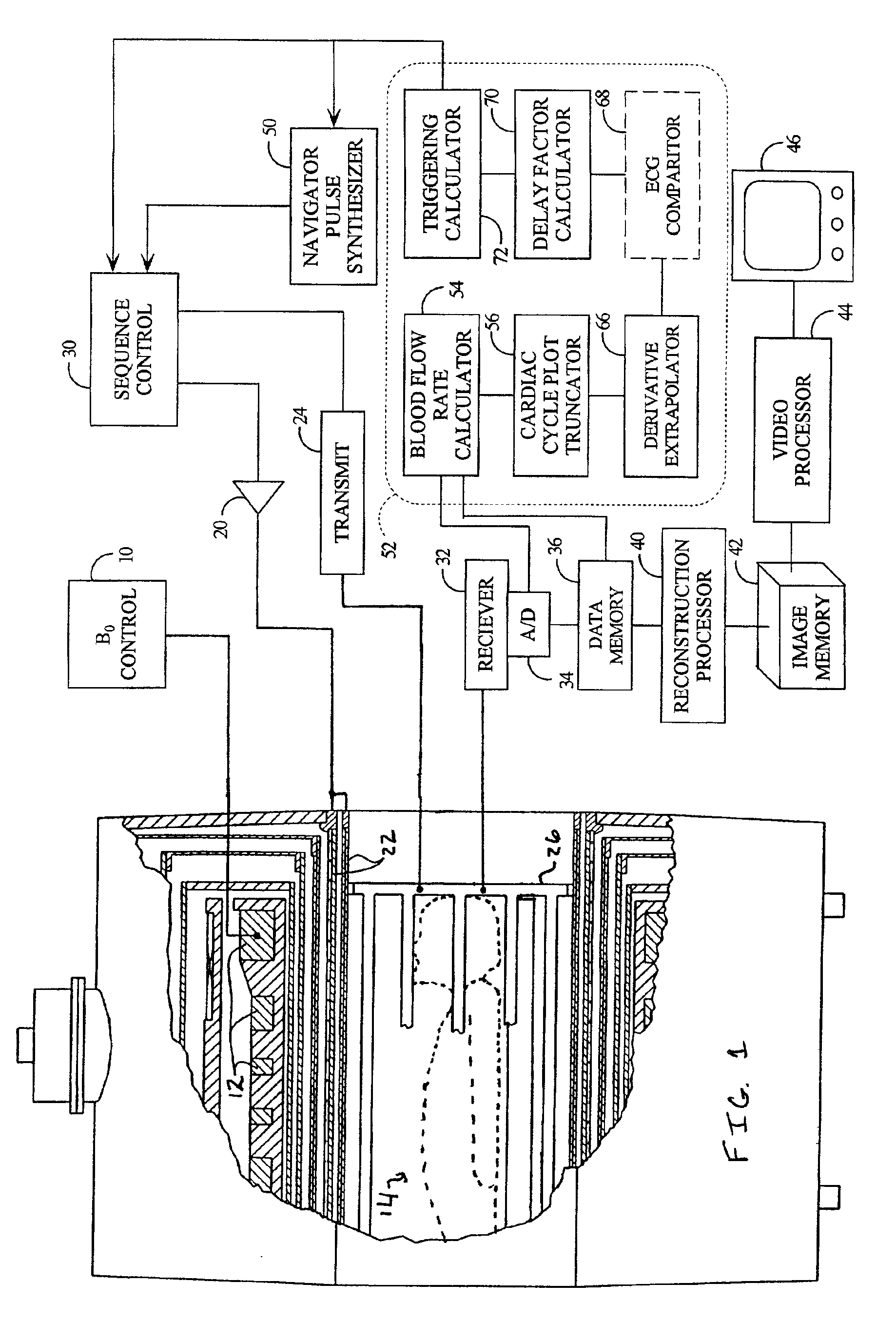
[0021]With reference to FIG. 1, a main magnetic field control 10 controls superconducting or resistive magnets 12 such that a substantially uniform, temporally constant main magnetic field is created along a z axis through an examination region 14. A magnetic resonance generation and manipulation system applies a series of radio frequency (RF) and magnetic gradient field pulses to re-orient the magnetization or excite magnetic spins, induce magnetic resonance, refocus magnetic resonance, manipulate magnetic resonance, spatially and otherwise encode the magnetic resonance, to saturate spin, and the like to generate magnetic resonance imaging and spectroscopy sequences. More specifically, gradient pulse amplifiers 20 apply current pulses to selected ones or pairs of whole-body gradient coils 22 to create magnetic field gradients along x, y and z-axes of the examination region 14. A digital radio frequency transmitter 24 transmits radio frequency pulses or pulse packets to a whole-body...


PUM


Abstract

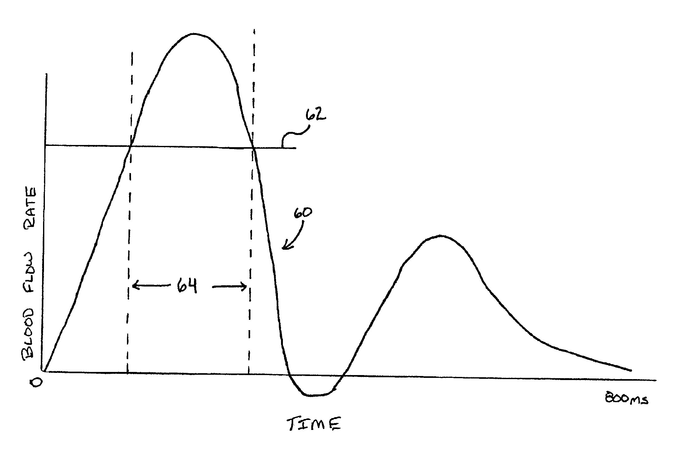
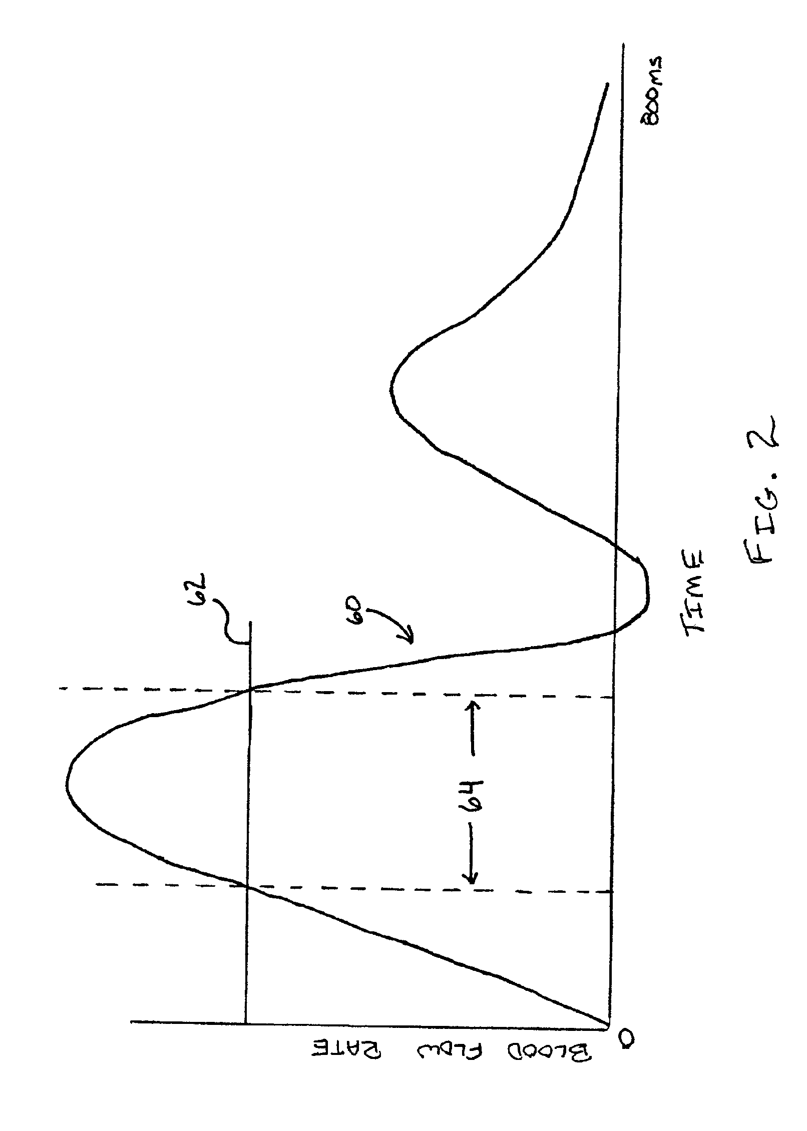
A magnetic resonance imaging method and apparatus includes a navigator region defined within the subject by selective excitation. Blood flow is measured within the selected region using the principles of phase contrast MR angiography. A cardiac cycle plot is constructed from Fourier transformed data that represents measured velocity of blood flow through the navigator region as a function of time. On the basis of the cardiac cycle plot and the navigator measurements, data acquisition is synchronized or gated to portions of the cardiac cycle.

Description

BACKGROUND OF THE INVENTION[0001]The present invention relates to the magnetic resonance imaging arts. It finds particular application in conjunction with imaging triggered from the cardiac cycle and will be described with particular reference thereto. It is to be appreciated, however, that the present invention may also find application in other cardiac gated applications, gated imaging triggered by other moving fluids or tissues, and the like.[0002]In magnetic resonance imaging, a substantially uniform main magnetic field is generated within an examination region. The main magnetic field polarizes the nuclear spin system of a patient being imaged within the examination region. Magnetic resonance is excited in the polarized dipoles by B1 fields generated from radio frequency excitation signals throughout the examination region. Specifically, radio frequency pulses tip the dipoles out of alignment with the main magnetic field and cause the macroscopic magnetic moment to precess arou...

Claims


Application Information

Patent Timeline
IPC IPC(8): A61B5/055G01R33/567G01R33/54A61B5/026G01R33/563
CPCA61B5/055A61B5/7285G01R33/5676A61B5/0263A61B5/7257A61B5/7289A61B5/7292G01R33/56316
Inventor DEMEESTER, GORDON D.LIU, KECHENG
Owner KONINKLIJKE PHILIPS ELECTRONICS NV
Learn More