Pilotless catalytic combustor

a combustor and pilot technology, applied in the direction of machines/engines, lighting and heating apparatus, furnaces, etc., can solve the problems of increasing the generation of oxides of nitrogen, complicated design of the combustor of the turbine engine, and low power operation at lower combustion temperatures

Inactive Publication Date: 2005-08-02
SIEMENS ENERGY INC
View PDF10 Cites 66 Cited by
  • Summary
  • Abstract
  • Description
  • Claims
  • Application Information

AI Technical Summary

Problems solved by technology

However, the LCL technique requires precise control of fuel and air volumes and may require the use a complex preburner to bring the fuel / air mixture to lightoff conditions.
The design of a turbine engine combustor is further complicated by the necessity for the engine to operate reliably with a low level of emissions at a variety of power levels.
High power operation at high firing temperatures tends to increase the generation of oxides of nitrogen.
Low power operation at lower combustion temperatures tends to increase the generation of carbon monoxide and unburned hydrocarbons due to incomplete combustion of the fuel.
A relatively rich fuel / air mixture will improve the stability of the combustion process, but will have an adverse affect on the level of NOx emissions.
However, pilot nozzles may produce a significant portion of the NOx produced by the combustion engine.
In addition, the mechanical intricacy of a pilot flame nozzle and fueling of the pilot flame introduce undesirable expense and complexity to the combustor.
However, a centrally located pilot is still required in the combustor of the '085 patent, resulting in undesirable NOx production.

Method used


Image

  • Pilotless catalytic combustor
  • Pilotless catalytic combustor

Examples


Embodiment Construction

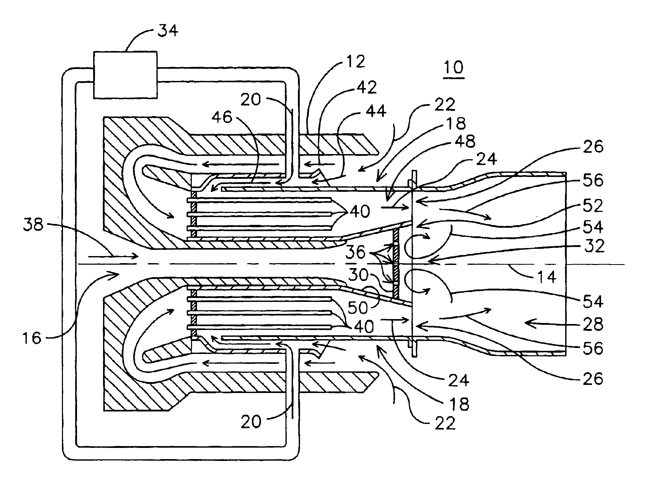
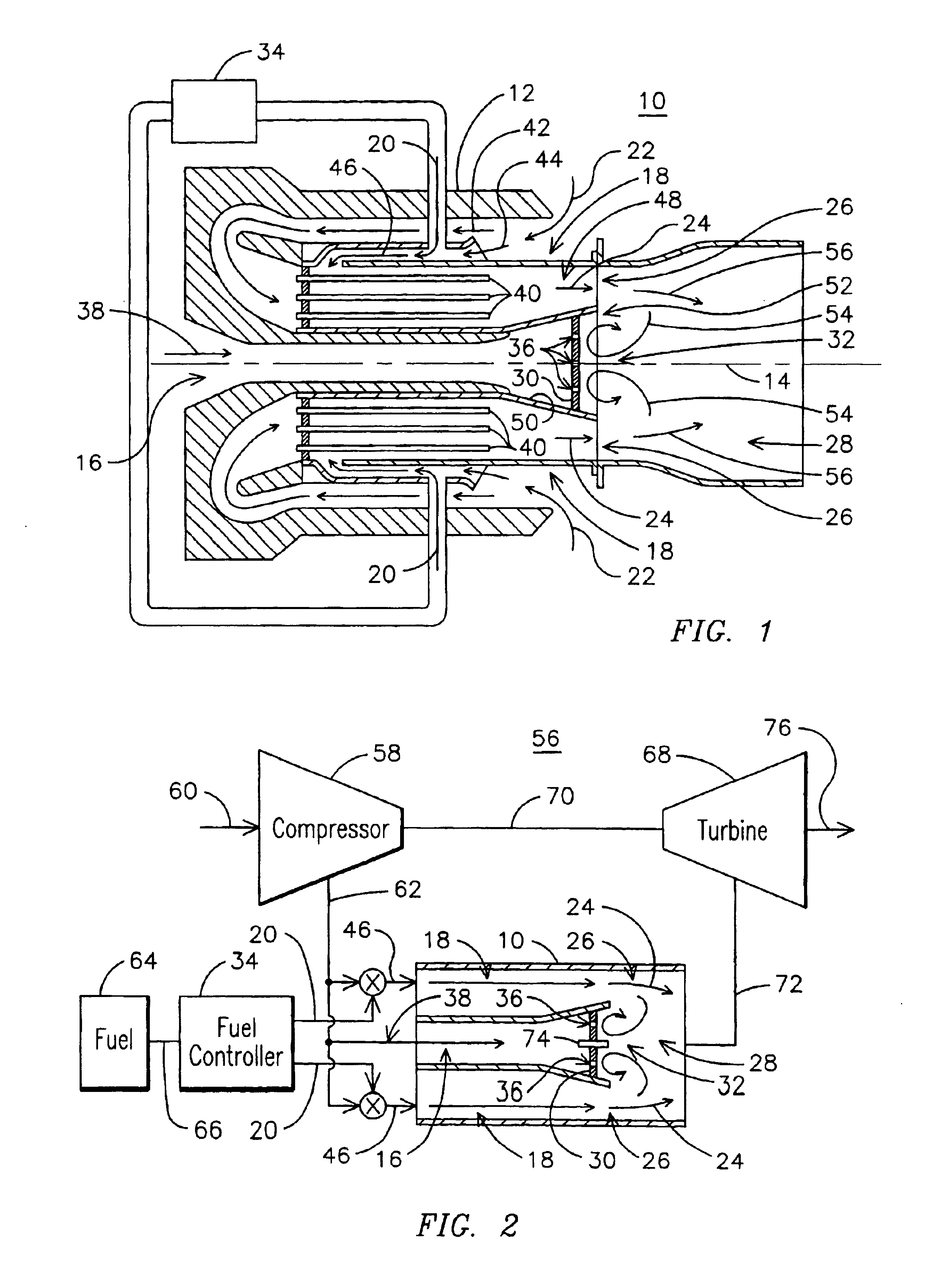
[0009]FIG. 1 illustrates a cross section of a pilotless combustor 10 including a plurality of catalytic combustion modules 18 arranged around a central core region 16. The combustor includes a combustor basket 12 having a central axis 14 for retaining the combustion modules 18 circumferentially installed in the combustor basket 12, radially outward of the central core region 16. Each combustion module 18 receives a fuel flow 20 and a first portion of an oxidizer flow 22. In a backside cooling embodiment, the first portion of an oxidizer flow 22 may be split into an oxidizer mixing flow 44 for mixing with the fuel flow 20 and a oxidizer cooling flow 42 for cooling catalytic elements 40. For example, the catalytic elements 40 may include tubes coated with a catalyst on a tube outside diameter surface. The oxidizer mixing flow 44 and the fuel flow 20 can be mixed to form a fuel / oxidizer mixture 46. In one aspect of the invention, the fuel / oxidizer mixture 46 is directed to flow around ...


PUM


Abstract

A pilotless catalytic combustor (10) including a basket (12) having a central axis (14) and a central core region (16) disposed along a portion of the central axis. Catalytic combustion modules (18) are circumferentially disposed about the central axis radially outward of the central core region for receiving a fuel flow (20) and a first portion of an oxidizer flow (22), and discharge a partially oxidized fuel / oxidizer mixture (24) at respective exit ends (26). A base plate (30) is positioned in the central core region upstream of the exit ends of the catalytic combustion modules, the baseplate defining a recirculation zone (32) near the respective exit ends for stabilizing oxidation in the burnout zone. A method of staged fueling for a pilotless catalytic combustor includes providing fuel to at least one of the modules during start up and progressively providing fuel to other modules as a load on the turbine engine is increased.

Description

FIELD OF THE INVENTION[0001]This invention relates generally to combustion turbine engines, and, in particular, to a pilotless catalytic combustor having staged fueling.BACKGROUND OF THE INVENTION[0002]It is known to use catalytic combustion in combustion turbine engines to reduce NOx emissions. One such catalytic combustion technique known as lean catalytic, lean burn (LCL) combustion, involves completely mixing fuel and air to form a lean fuel mixture that is passed over a catalytically active surface prior to introduction into a downstream combustion zone. However, the LCL technique requires precise control of fuel and air volumes and may require the use a complex preburner to bring the fuel / air mixture to lightoff conditions. An alternative catalytic combustion technique is the rich catalytic, lean burn (RCL) combustion process that includes mixing fuel with a first portion of air to form a rich fuel mixture. The rich fuel mixture is passed over a catalytic surface and mixed wit...

Claims


Application Information

Patent Timeline
Patent Type & Authority Patents(United States)
IPC IPC(8): F23R3/40F23R3/00
CPCF23R3/40F23C2900/13002
Inventor LASTER, WALTER RAYBANDARU, RAMARAO V.
Owner SIEMENS ENERGY INC
Why Eureka
Try Eureka