Device and method for flame stabilization in a burner

a technology of flame stabilization and burner, which is applied in the direction of catalytic material combustion, combustion types, furnaces, etc., can solve the problems of inability to form spatially stationary flames, inability to use generic premix burners, etc., to achieve the effect of increasing design flexibility in construction and increasing nitrogen oxide emission

Inactive Publication Date: 2008-12-23
ALSTOM TECH LTD
View PDF13 Cites 74 Cited by
  • Summary
  • Abstract
  • Description
  • Claims
  • Application Information

AI Technical Summary

Benefits of technology

[0015]One aspect of the present invention includes a device and a method for flame stabilization of a flame developing downstream of a premix burner in such a way that the measures used for the stabilization are neither capable of lastingly impairing the flame stability, i.e., the flame location, nor of leading to an increased nitrogen oxide emission. On the contrary, it should be possible to take flame-stabilizing measures which in the main do not depend on burner design and do not lastingly impair the combustion characteristics optimized by the burner concept. Therefore, the measures to be taken are to help to create an increased design flexibility in the construction of premix burners and, moreover, be applicable to as many different burner systems as possible without having to take into account requirements with regard to a special system optimization.
[0018]A method principle forming a basis of the device embodying principles of the present invention is based on a flame stabilization with the aid of a chemically inert hot gas flow of at least 600° C., and preferably up to 950° C., which is introduced into the combustion chamber in or adjacent to the flame. The hot, non-reacting gas brings about a thermal stabilization of the homogenized flame developing inside the combustion chamber, wherein the inert nature of the hot, hot gas components makes it possible to feed the inert hot gas flow at any point inside the burner system to that in the flame region without, as a consequence, altering the flame position and the mixing times associated with it, nor giving rise to increased nitrogen oxide formation. By such exemplary measures, an unprecedented degree of design flexibility is created which allows a device constructed according to principles of the present invention, which has a so-called two-stage pilot catalyst, to be combined with the most varied burner systems, largely without, as a consequence, having to take into account optimization requirements which would be bound by special system constraints.

Problems solved by technology

On the contrary, the problem relates to all generic premix burners.
Such burners are, however, unavoidable if operated even only temporarily under load- and operating conditions, under which a homogenously developing, spatially stationary flame cannot be formed or can be formed only with considerable limitations.
To sum up, it can consequently be emphasized that problems face the previously described measures for flame stabilization during the operation of modern premix burners, especially under partial load conditions or during the starting phase.
On the other hand, the piloting technique previously in use influences the flame position and thus the available time for the complete mixing of the air / fuel mixture which with premature ignition releases a considerable nitrogen oxide portion.

Method used


Image

  • Device and method for flame stabilization in a burner
  • Device and method for flame stabilization in a burner
  • Device and method for flame stabilization in a burner

Examples


Embodiment Construction

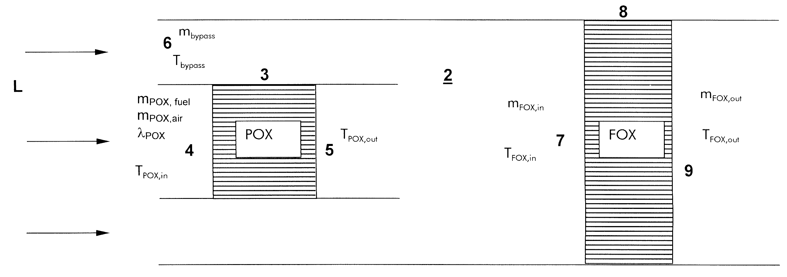
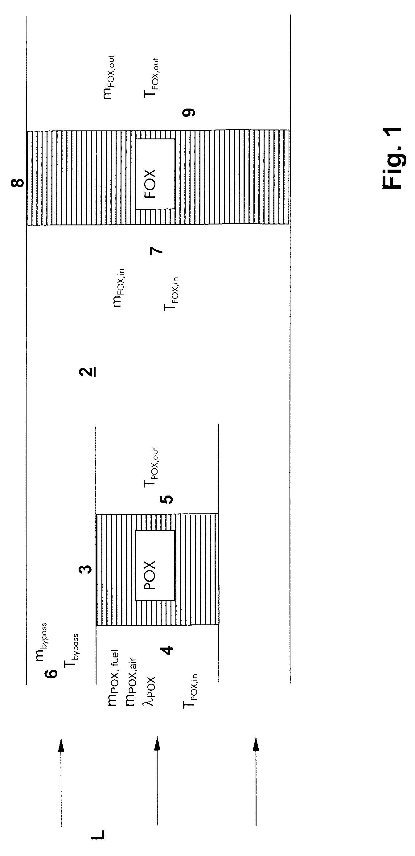
[0026]The schematized view represented in FIG. 1 shows a catalyst arrangement 1 embodying principles of the present invention which includes a flow passage 2 through which passes an air flow L from left to right in the drawing. Provided inside the catalyst arrangement centrally upstream of the flow passage 2 is a first catalyst 3, the so-called POX-catalyst, which has a plurality of catalyst passages orientated in the flow direction and which are lined on the inner wall with suitably selected catalyst material and is specially selected for the catalysis of a rich air / pilot fuel mixture. The POX-catalyst 3 on the upstream side is fed by an air / pilot fuel mixture 4, which consists of a completely mixed fuel flow mPOX,fuel and an air flow mPOX,air. The air / pilot fuel mixture 4 entering the POX-catalyst 3 is provided with an adjustable mixture ratio λPOX as well as a specifically adjustable mixture inlet temperature TPOX,in. Because, as already mentioned, the flow passages of the POX-ca...


PUM


Abstract

A device and a method for flame stabilization in a burner (10), includes a burner housing at least partially enclosing a burner volume, into which may be introduced via at least one fuel line, fuel, and via at least one air feed means, air, forming an air / fuel mixture spreading in a preferred flow direction, which may be ignited in a combustion chamber (11) connecting downstream of the burner housing to form a stationary flame (13). Upstream of the flame (13), a catalyst arrangement (1) is provided through which an air / pilot fuel mixture (4), separate from the air / fuel mixture, is flowable. The catalyst arrangement (1) has at least two catalyst stages which are located one behind the other in the through-flow direction, of which the catalyst stage (3) located upstream, the so-called POX-catalyst, is flow-washable by the air / pilot fuel mixture (4) with an air / pilot fuel mixture ratio λ<1, by which catalyst stage (3) the air / pilot fuel mixture (4) is partially oxidized, and of which catalyst stages the downstream catalyst stage (8), the so-called FOX-catalyst, is flow-washable by a leaned air / pilot fuel mixture (7) with a mixture ratio λ>1, by which the leaned air / pilot fuel mixture is completely oxidized forming an inert hot gas flow (9).

Description

[0001]This application is a Continuation of, and claims priority under 35 U.S.C. § 120 to, International application number PCT / EP2005 / 051333, filed 23 Mar. 2005, and claims priority under 35 U.S.C. § 119 to German application number 10 2004 015 607.7, filed 30 Mar. 2004, the entireties of both of which are incorporated by reference herein.BACKGROUND OF THE INVENTION[0002]1. Field of the Invention[0003]The invention refers to a device for flame stabilization in a burner, with a burner housing at least partially enclosing a burner volume into which may be introduced via at least one fuel line, fuel, and via at least one air feed means, air, forming an air / fuel mixture spreading in a preferred flow direction, which air / fuel mixture may be ignited in a combustion chamber connecting downstream of the burner housing to form a stationary flame. In addition, a method for flame stabilization in a burner related to this is described.[0004]2. Brief Description of the Related Art[0005]Modern p...

Claims


Application Information

Patent Timeline
Patent Type & Authority Patents(United States)
IPC IPC(8): F23D3/40F23C13/00F23R3/40
CPCF23C13/00F23R3/40F23C2900/13002
Inventor CARRONI, RICHARDMEEUWISSEN, THIEMO
Owner ALSTOM TECH LTD
Why Eureka
Try Eureka