Method for transferring cryogenic liquids and associated cryogenic fill nozzle insulating boot

a technology of insulating boot and liquid, which is applied in the direction of gas/liquid distribution and storage, lighting and heating apparatus, applications, etc., can solve the problems of moisture escaping from the ambient environment, moisture frothing on the surface of containment material, and affecting the operation of the containment material, so as to reduce the downtime or repair and maintenance time, reduce the cost and the effect of downtim

Inactive Publication Date: 2005-08-02
WESTPORT POWER
View PDF6 Cites 7 Cited by
  • Summary
  • Abstract
  • Description
  • Claims
  • Application Information

AI Technical Summary

Benefits of technology

[0033]The present technique adapts an insulating material or removable boot that alone needs to be replaced when it fails, thereby reducing costs and downtime or repair and maintenance time while extending the available materials that can be used in such a boot.
[0034]Also downtime from breaking ice between surfaces is significantly reduced.
[0035]The solution also takes advantage of the nozzle

Problems solved by technology

Problems can arise from heat transfer between the liquid or gas environment through the containment material used to hold the liquid or gas.
One such problem is that moisture within the ambient environment may be released from that environment and, if the temperature of the gas or liquid is low enough, that moisture may be frozen onto the surface of the containment material.
Where moving parts are found within the containment material or where an interface exists between two detachable parts of the containment material, as is the case with nozzle attachments used to join lines for transferring liquid or gas between holding tanks, such parts can be difficult to move or detach, as the case may be, when moisture has frozen in and around those parts.
By way of example, such a problem arises where liquefied or cryogenic gases are being transferred between holding vessels.
Equally, moisture that has seeped into the moving parts or abutting interfaces of the nozzle may freeze, thereby restricting movement of those moving parts.
This can create an accumulation of moisture on the surfaces of these parts over the course of several transfers.
If this moisture then freezes on the surfaces that define this abutting interface and across the interface, it can be difficult to detach the nozzle from the receiving line.
One cryogenic operation that can experience the problems noted above arises when refueling natural gas powered vehicles that

Method used


Image

  • Method for transferring cryogenic liquids and associated cryogenic fill nozzle insulating boot
  • Method for transferring cryogenic liquids and associated cryogenic fill nozzle insulating boot
  • Method for transferring cryogenic liquids and associated cryogenic fill nozzle insulating boot

Examples


Embodiment Construction

)

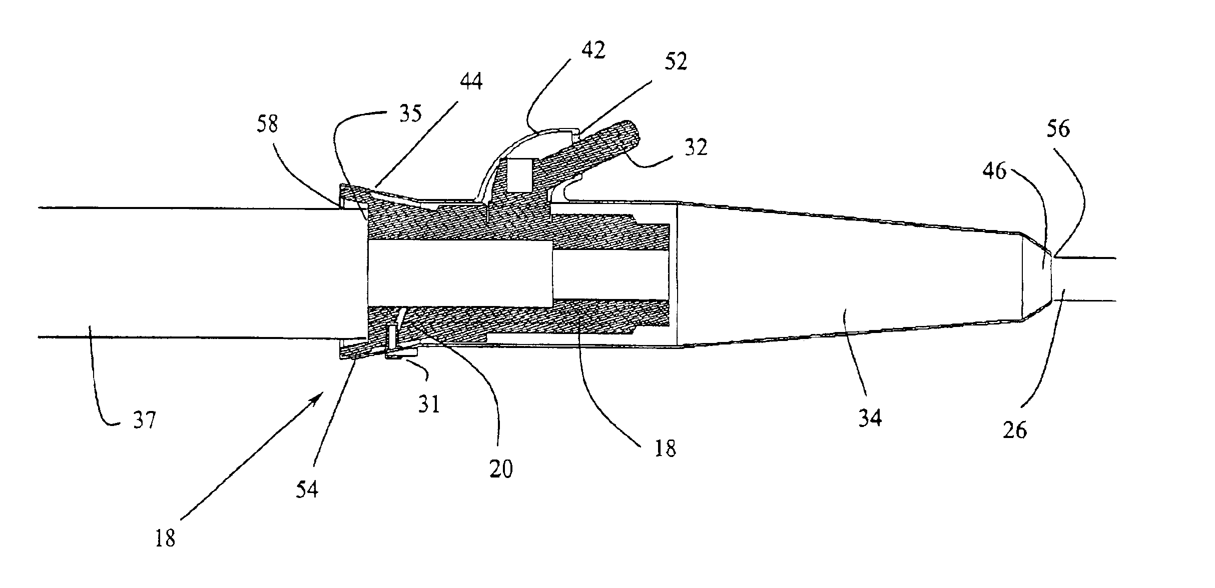
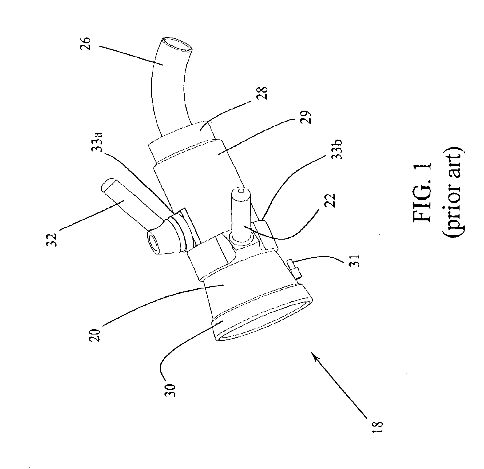
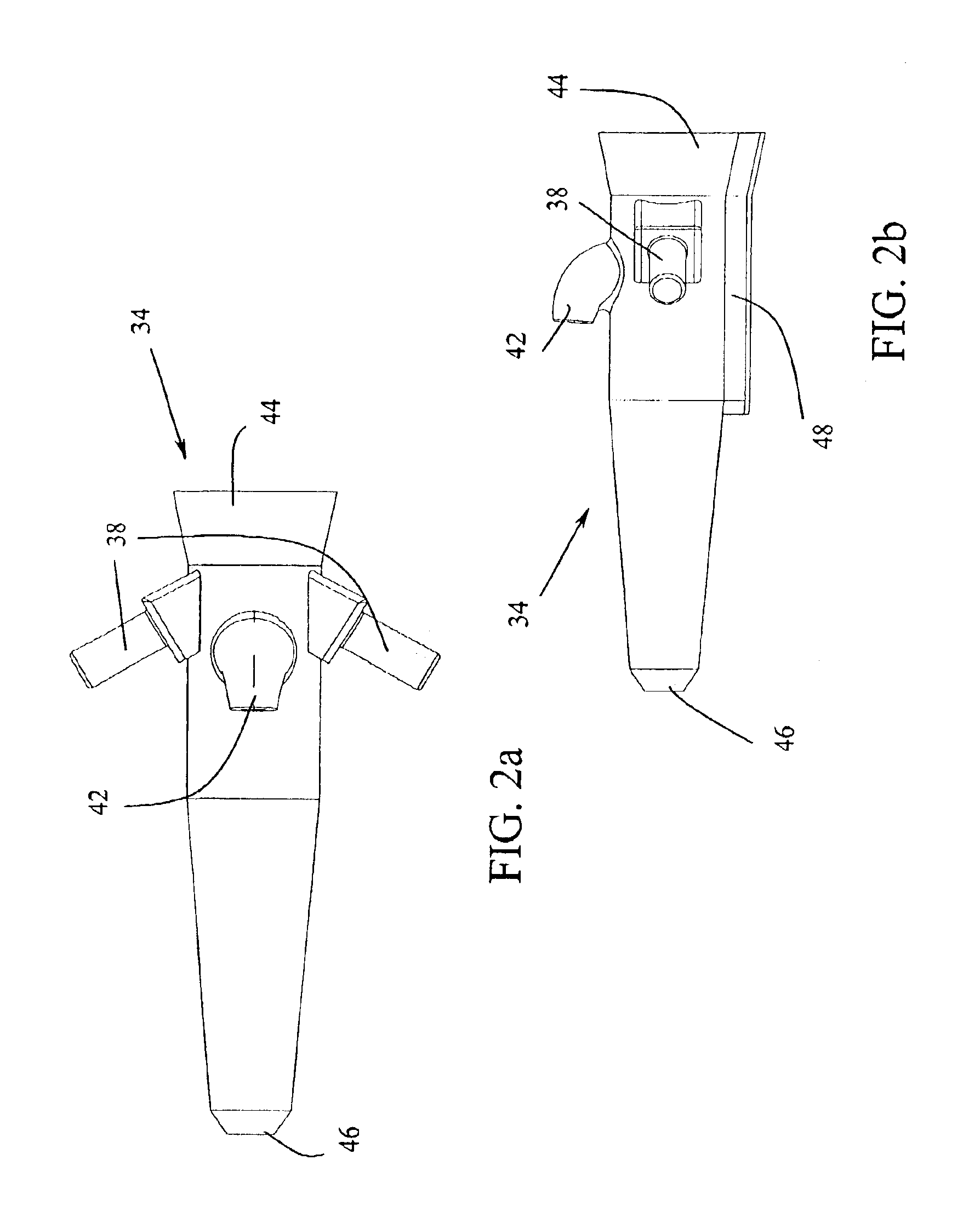
[0042]In the present method, a removable boot is adapted to a cryogenic nozzle used to transfer a quantity of LNG between holding tanks. The nozzle is then removably fitted to a receiving line connected to the tank to be filled. The nozzle is then purged of moisture within any moving parts of the nozzle as well as the abutting interface between the nozzle and the receiving line. This is done, generally, where a flow of a dry gas such as nitrogen is sent through an access line in the nozzle that leads to the interface and moving parts. The nitrogen then flows out of the nozzle into the layer between the nozzle and the boot. As the boot provides a restrictive seal around the nozzle, it will allow a small quantity of nitrogen, under pressure, to escape carrying any moisture out of the nozzle, from the abutting interface and from the layer. If dry gas flow is maintained, moisture will be restricted from entering into the layer. Once moisture is purged from the nozzle and abutting inter...


PUM


Abstract

In the present method, cold substances are transferred through a nozzle with moving parts. An insulating boot facilitates the method. The present method is generally suited for use in transferring cryogenic substances such as during the refueling of liquid natural gas vehicles. The present method causes an insulating layer to be created between a removable boot and a nozzle separating the ambient environment from the moving parts of the nozzle, purging the layer with a dry gas such as nitrogen to remove moisture and restricting the incursion of such moisture from the layer and therefore, from the moving parts to avoid freezing up of the moving parts. The layer can also help to avoid freezing up of the abutting interface created between the nozzle and receiving line when the nozzle is removably engaged to a receiving line.

Description

FIELD OF THE INVENTION[0001]The present invention relates to a method of transferring cryogenic liquids and an associated removable insulating boot adaptable to a cryogenic nozzle.BACKGROUND OF THE INVENTION[0002]When handling liquids or gases at temperatures below an ambient or background temperature, special care should be taken to thermally insulate the ambient environment from the liquid or gaseous environment. Problems can arise from heat transfer between the liquid or gas environment through the containment material used to hold the liquid or gas. One such problem is that moisture within the ambient environment may be released from that environment and, if the temperature of the gas or liquid is low enough, that moisture may be frozen onto the surface of the containment material. Where moving parts are found within the containment material or where an interface exists between two detachable parts of the containment material, as is the case with nozzle attachments used to join ...

Claims


Application Information

Patent Timeline
IPC IPC(8): F17C13/00F17C5/00F17C13/10
CPCF17C5/007F17C13/10F17C2205/0329F17C2205/0355F17C2223/0161F17C2223/033F17C2227/0309F17C2227/039F17C2260/032F17C2265/065F17C2270/0139
Inventor BROOK, THOMAS CURRIECHAMBERS, SAMUEL DOUGLAS
Owner WESTPORT POWER
Why Eureka
Try Eureka