Fluid processing device with annular flow paths

a technology of fluid processing device and annular flow path, which is applied in the direction of mechanical equipment, water supply installation, transportation and packaging, etc., can solve the problems of movement or vibration of the cylindrical rod which defines the inner diameter of the annular flow path, and achieve the effect of restoring the pressure balan

Inactive Publication Date: 2005-08-02
IMATION
View PDF14 Cites 10 Cited by
  • Summary
  • Abstract
  • Description
  • Claims
  • Application Information

AI Technical Summary

Benefits of technology

[0006]In some embodiments, the cylindrical rod may be free to move and vibrate within the flow path cylinder, which can provide an automatic anti-clog mechanism. In other words, if particles in the mixture become clogged inside the fluid processing device, the cylindrical rod which defines the inner diameter of the annular flow path can move or vibrate as a result of pressure imbalance caused by the clog. The movement of the cylindrical rod, in turn, may help to clear the clogged material and restore the pressure balance within the fluid processing device.
[0014]The invention may be capable of providing a number of advantages. In general, the invention may improve industrial manufacturing of coatings, inks, paints, and the like. In particular, the use of annular flow paths may improve the shearing of particles in a mixture, producing particles with reduced size and possibly enhanced size uniformity. In particular, annular flow paths may enhance wall shear forces in the fluid processing device, e.g., because of increased wall surface area for a given flow path. The invention may be capable of handling input pressures on the order of approximately 60,000 psi (413 MPa). In addition, the invention may provide automatic anti-clog features that can improve the industrial manufacturing process by reducing or avoiding the need to manually clean and de-clog the fluid processing device. Thus, the automatic anti-clog features can reduce maintenance costs and avoid down-time of the manufacturing system. Also, the invention may improve the end product in terms of reduced particle sizes and improve particle size uniformity.

Problems solved by technology

In other words, if particles in the mixture become clogged inside the fluid processing device, the cylindrical rod which defines the inner diameter of the annular flow path can move or vibrate as a result of pressure imbalance caused by the clog.

Method used


Image

  • Fluid processing device with annular flow paths
  • Fluid processing device with annular flow paths
  • Fluid processing device with annular flow paths

Examples


Embodiment Construction

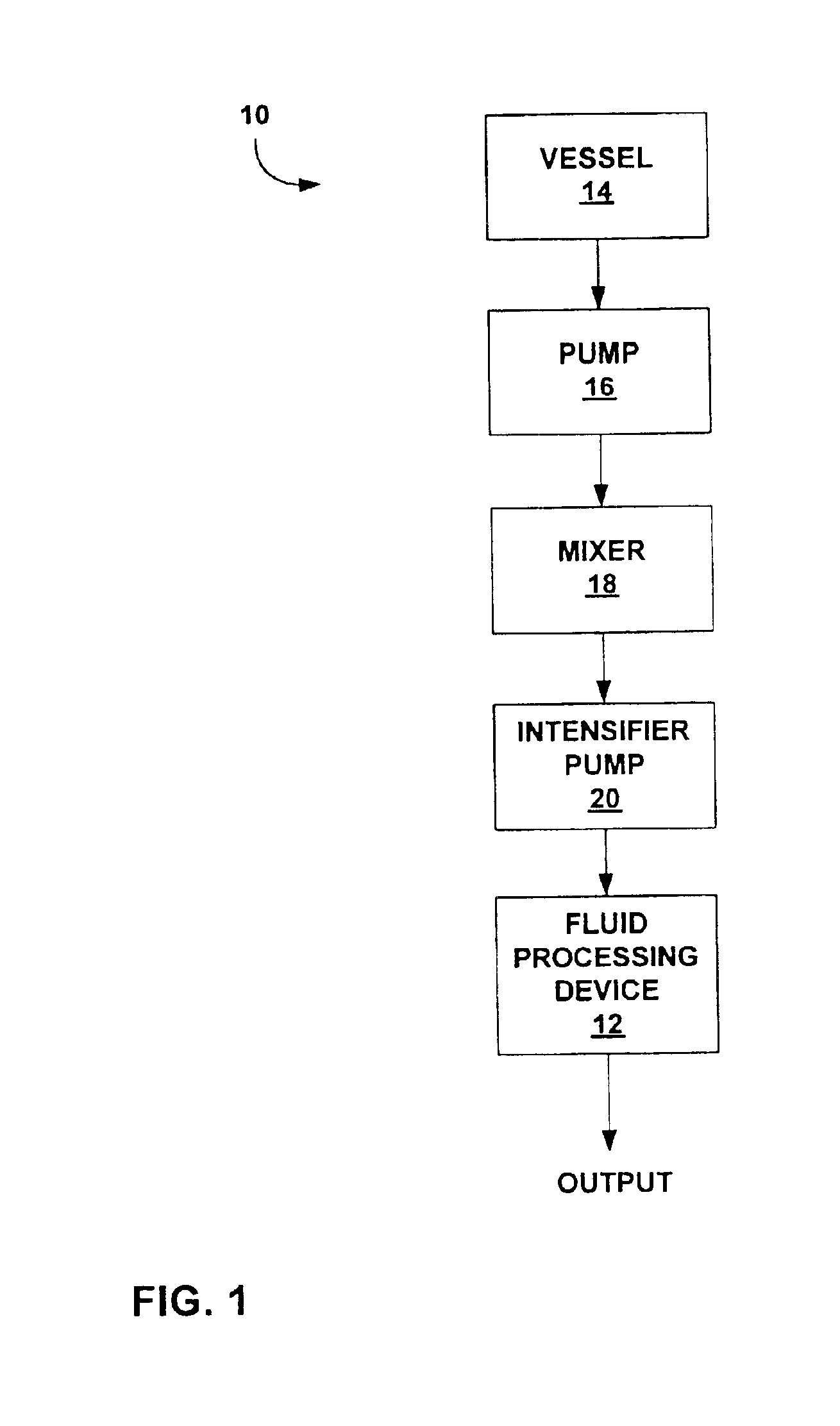
[0020]FIG. 1 is a block diagram of an exemplary industrial fluid processing system 10. System 10 may incorporate a fluid processing device 12 with opposing annular flow paths, as further described herein. System 10, with fluid processing device 12, may be particularly useful in processing coating solutions having high concentrations of solids. For example, system 10 may be used to process coating solutions having solid particle contents of greater than approximately ten percent by weight, although the invention is not limited in that respect. For some industrial applications, the coating solution may carry hard, substantially non-compliant particles, such as magnetic pigments used for coating of magnetic media. System 10 may also be used for other industrial processes including, for example, the preparation of inks, paints, abrasive coatings, and the like.

[0021]As shown in FIG. 1, a vessel 14 stores one or more solvents, one or more collections of particles, and optionally other mat...


PUM

PropertyMeasurementUnit
widthaaaaaaaaaa
widthaaaaaaaaaa
widthaaaaaaaaaa

Abstract

The invention is directed to a high pressure fluid processing device for shearing particles in a fluid mixture. The fluid processing device makes use of annular flow paths. For example, a fluid mixture can be separated into two flow paths which are introduced to first and second annular flow paths on opposite sides of a flow path cylinder. The two annular flow paths flow toward one another through the cylinder, and meet one another within the cylinder. An outlet extends through the cylinder where the two annular flow paths collide allowing the fluid mixture flowing down the annular flow paths to be expelled through the gap.

Description

TECHNICAL FIELD[0001]The invention relates to fluid processing and, more particularly, high pressure fluid processing devices for creating particulate structures in a fluid mixture.BACKGROUND[0002]The creation and processing of hard, non-compliant particles in a fluid mixture is desirable for a variety of industrial processes including, for example, the preparation of inks, paints, abrasive coatings, and the like. In addition, fluid mixtures of hard particles are used extensively in the coating of magnetic media, such as magnetic disks, magnetic tape or other magnetic media used for data storage. For magnetic media, the mixture may contain magnetic particles and a polymeric binder carried in a solvent. The coating process involves application of the mixture to a substrate, followed by a drying process to remove the solvent.[0003]For high-density magnetic media and other industrial processes, the size and uniformity of the various particles is extremely important. To produce particle...

Claims


Application Information

Patent Timeline
Patent Type & Authority Patents(United States)
IPC IPC(8): B01F15/00B01F3/12B01F5/02
CPCB01F3/1207B01F5/0256B01F5/0262B01F15/00019B01F2215/0431B01F2215/0468Y10T137/87676Y10T137/87652B01F23/51B01F25/231B01F25/23B01F35/145
Inventor SERAFIN, MARKNELSON, NEAL K.ELLIS, STANLEY R.
Owner IMATION
Why Eureka
Try Eureka