
Vacuum device and method for treating tissue adjacent a body cavity

a vacuum device and tissue technology, applied in the field of medical treatment devices and methods, can solve the problems of affecting the normal size and shape of the tissue cavity, the inability to uniformly and uniformly distribute the treatment material, and the deleterious effects of radiation treatment, etc., to achieve the effect of reducing “hot spots", reducing radiation radiation intensity, and controlling the distance from the treatment material

Inactive Publication Date: 2005-08-02
HOLOGIC INC
View PDF18 Cites 220 Cited by
  • Summary
  • Abstract
  • Description
  • Claims
  • Application Information

AI Technical Summary

Benefits of technology

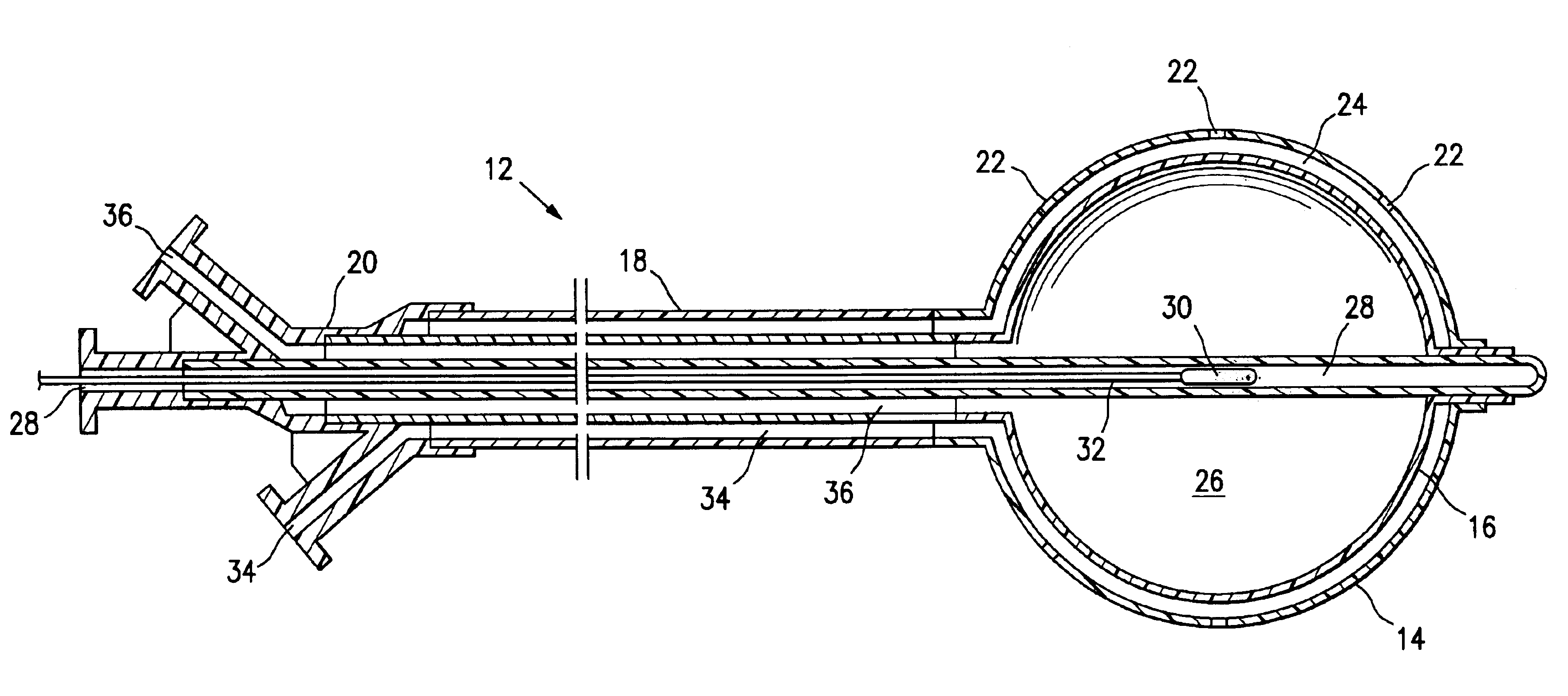
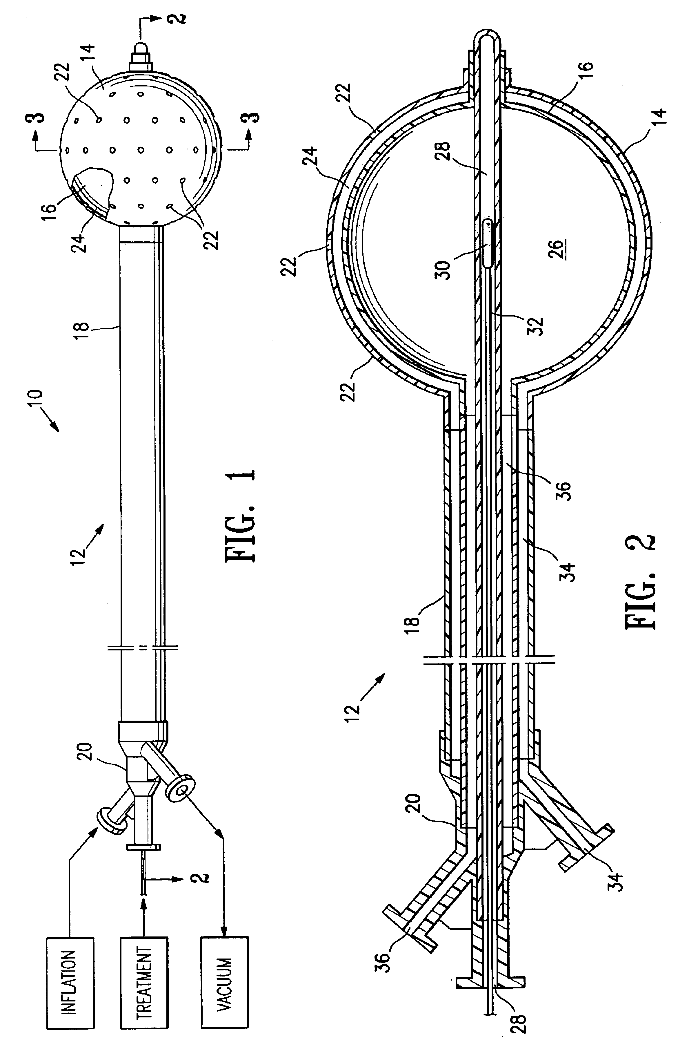
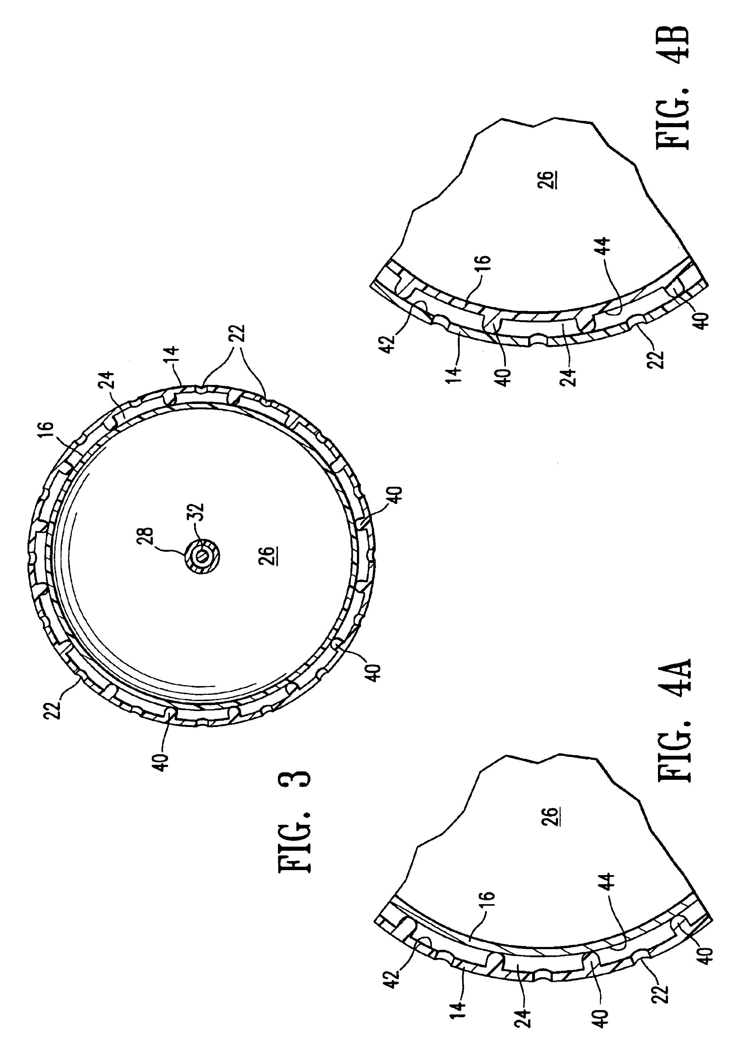
[0010]Devices may further include an enclosure assembly (which may comprise a sheath assembly or a balloon assembly) comprising a vacuum conduit and a fluid-permeable enclosure wall (e.g., a sheath wall or a balloon wall) configured to partly or completely enclose an inner balloon assembly. Such an enclosure assembly may be effective to provide vacuum and a vacuum path to an intermediate space outside the inner balloon assembly. An intermediate space may include a space disposed between the inner balloon assembly and a sheath assembly or an outer balloon assembly. The enclosure assembly is preferably operatively connected to a vacuum conduit effective to provide vacuum to the intermediate space. Systems having features of the invention include such devices and further include a vacuum source configured to operatively connect with the vacuum conduit. In embodiments of devices having features of the invention, a fluid-permeable enclosure wall may have a hole or multiple holes configured to allow passage of fluid, may be made with a fluid-permeable material, such as a fluid-permeable woven material, or may be otherwise fluid-permeable. The space between the inner balloon and the enclosure may be prevented from collapse, even in the presence of suction from a vacuum delivered via the vacuum conduit, by separation elements disposed on the inner balloon wall, or on the enclosure wall, or both. In alternative embodiments, separation elements disposed within an intermediate space may be independent of both the inner balloon wall and the enclosure wall.
[0015]Body cavities are typically not uniform in size or regular in shape. Devices, systems and methods having features of the invention utilize suction to draw tissue against the device surface within a body cavity, insuring good contact between the device and body tissue and providing control over the spacing between tissue and the device, including control over the distance from the treatment material contained within the devices. Tissue lining a body cavity that is held close to, or in contact with, devices having features of the invention forms a uniform and controlled surface, unlike tissue lining a body cavity in which a prior art treatment device has been merely inserted, but which does not urge tissue into a desired orientation and position. The control over the distance, spacing, and amount of tissue contact provided by devices, systems and methods of the present invention offer the advantages of improved treatment tissue adjacent a body cavity. Such improvements may include more uniform dosing, reduction of “hot spots,” shorter treatments due greater correlation between desired and actual dosages, and reduction in the number of locations receiving inadequate dosages.

Problems solved by technology

However, radiation, chemotherapy, thermal treatment, and other cancer treatments often have deleterious effects on healthy tissue in addition to the desired effects on cancerous tissue.
However, tissue cavities typically are not uniform or regular in their sizes and shapes, so that differences in dosages applied to different regions of surrounding tissue, including “hot spots” and regions of relatively low dosage, often result from radiation treatment.

Method used


Image

  • Vacuum device and method for treating tissue adjacent a body cavity
  • Vacuum device and method for treating tissue adjacent a body cavity
  • Vacuum device and method for treating tissue adjacent a body cavity

Examples


Embodiment Construction

[0027]The present invention provides devices and methods for delivering a treatment, such as a cancer treatment, into a cavity within the body of an animal. For example, devices and methods having features of the invention may be used to deliver treatments into a biopsy site or into a cavity left after removal of cancerous tissue from within the body of a human patient. Vacuum is applied to tissue to enhance contact between a treatment delivery assembly within a body cavity and tissue surrounding the body cavity. A vacuum path around the treatment assembly is provided by devices, systems and methods embodying features of the invention. Vacuum may be applied to tissue via one, two, or multiple vacuum ports. A vacuum port may be a port in a vacuum delivery conduit, a hole in a sheath or balloon connected to a vacuum delivery conduit. A fluid permeable wall or portion of a fluid permeable wall may be effective to serve as a vacuum port.

[0028]FIG. 1 is a perspective view of a system 10 ...


PUM


Abstract

Devices and methods are provided for applying vacuum near to devices for delivering treatments to tissue adjacent a body cavity, effective to draw adjacent tissue near to such devices and to enhance treatment of the tissue. Body cavities include natural body cavities and cavities remaining after removal of tissue such as cancerous tissue. A device may include an inner balloon assembly with an inflation conduit. A sheath assembly having a fluid-permeable sheath wall may enclose the inner balloon assembly. Vacuum applied to the space between the sheath and the inner balloon is useful to draw tissue into contact with the device, improving treatment effectiveness. Methods for treating tissue with such devices and systems are also provided. Treatments may include providing radioactive material for radiation treatment, providing chemotherapeutic material for chemotherapy, providing thermal treatment, and combinations thereof. Systems may include devices of the invention and a vacuum source.

Description

FIELD OF THE INVENTION[0001]This invention relates generally to the fields of medical treatment devices and methods. In particular, the invention relates to devices and methods for treating tissue surrounding a body cavity, such as a site from which cancerous, pre-cancerous, or other tissue has been removed.BACKGROUND OF THE INVENTION[0002]In diagnosing and treating certain medical conditions, it is often desirable to perform a biopsy, in which a specimen or sample of tissue is removed for pathological examination, tests and analysis. A biopsy typically results in a biopsy cavity occupying the space formerly occupied by the tissue that was removed. As is known, obtaining a tissue sample by biopsy and the subsequent examination are typically employed in the diagnosis of cancers and other malignant tumors, or to confirm that a suspected lesion or tumor is not malignant. Treatment of cancers identified by biopsy may include subsequent removal of tissue surrounding the biopsy site, leav...

Claims


Application Information

Patent Timeline
IPC IPC(8): A61N5/10A61F2/958
CPCA61N5/1015A61B2017/22048A61B2017/22051
Inventor LUBOCK, PAUL
Owner HOLOGIC INC
Learn More