Device and Method for Accelerating Orthodontic Treatment Using Mechanical Vibrations

a mechanical vibration and orthodontic technology, applied in the field of orthodontics, can solve the problems of cutting off blood circulation, affecting the treatment effect, so as to increase the effect of treatment, shorten the treatment time, and reduce the effect of time and resources

Pending Publication Date: 2020-03-19
THE RES FOUND OF STATE UNIV OF NEW YORK
View PDF2 Cites 0 Cited by
  • Summary
  • Abstract
  • Description
  • Claims
  • Application Information

AI Technical Summary

Benefits of technology

[0013]The present disclosure provides an intra-oral vibrating device that is contained in the mouth (not visible). This device is capable of shortening and increasing the effectiveness of the orthodontic treatment. Shorter treatment time allows for devotion of time and resources from dental practices to each individual case. Therefore, the device is minimally invasive which increases the patient compliance during the treatment. Embodiments of the device utilize piezoelectric actuators that can be excited by a voltage function generator (signal generator) given a specific frequency and amplitude. The vibrating part of the device may be composed of a bio-compatible smart material such as polyvinylidene fluoride (PVDF). PVDF is an advantageous piezoelectric polymer because of its high flexibility, biocompatibility, and low cost. These features make PVDF attractive for energy conversion...

Problems solved by technology

Excessive force would lead to capillary collapse, cutting off blood circulation and leading to areas of tissue necrosis and thus root resorption.
Fixed orthodontic treatment also poses high risks of caries, external root resorption, and decreased patient compliance over time.
This makes them difficult and expensive to build, as well as uncomfortable to use, thus reducing patient compliance.
The vibration induced by the device increases the blood flow which increases the user's discomfort.
In another device, the bulkiness of the...

Method used


Image

  • Device and Method for Accelerating Orthodontic Treatment Using Mechanical Vibrations
  • Device and Method for Accelerating Orthodontic Treatment Using Mechanical Vibrations
  • Device and Method for Accelerating Orthodontic Treatment Using Mechanical Vibrations

Examples


Embodiment Construction

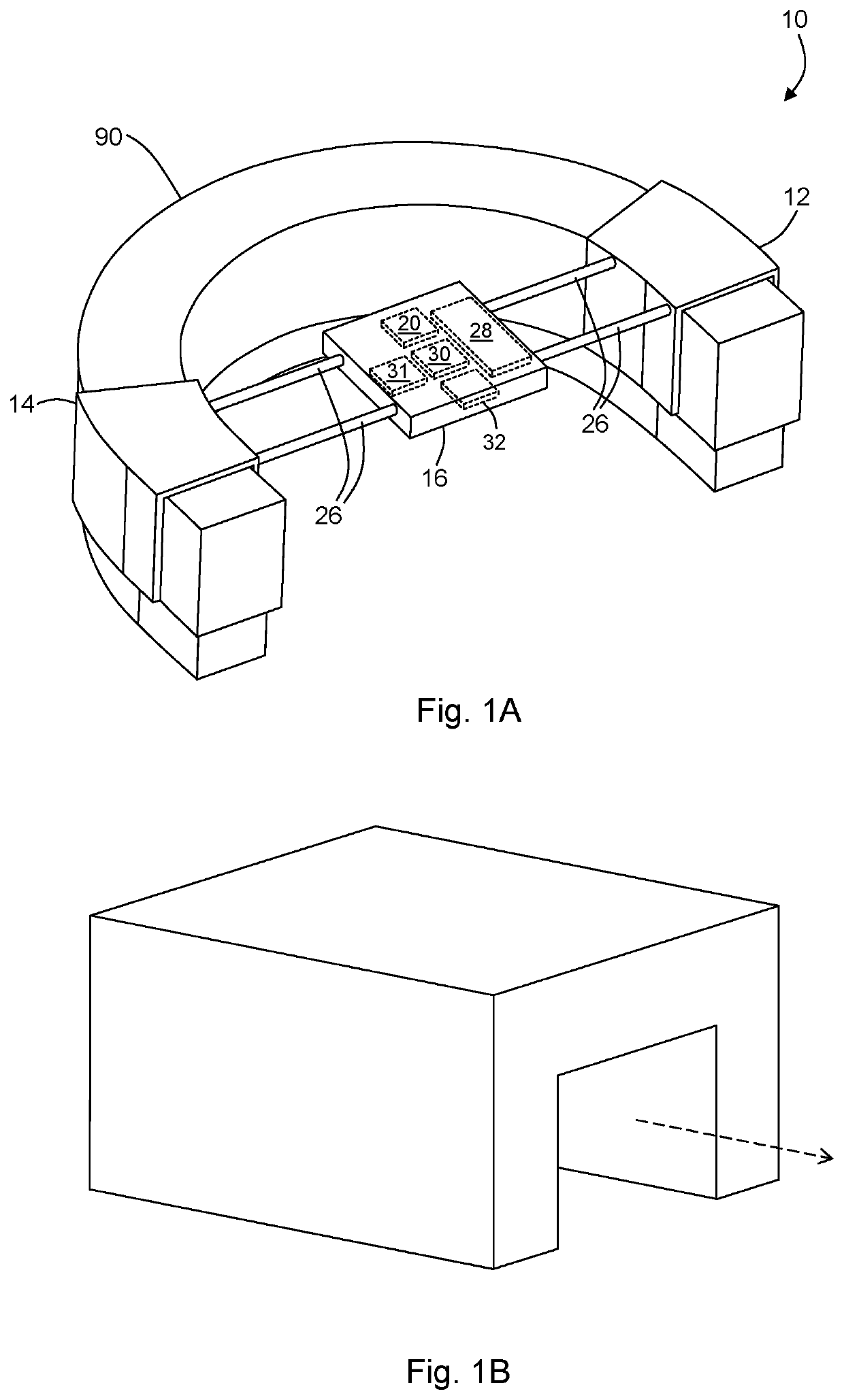
[0037]With reference to FIG. 1A, the present disclosure may be embodied as a vibrational device 10 for attachment to an orthodontic appliance 90. For example, the device 10 may be attached to a tooth positioner or aligner. The device 10 includes a first actuator 12 configured to be attached to the orthodontic appliance 90 at a location proximate to a dentition (e.g., a tooth or teeth being aligned). In this way, the first actuator 12 can impart vibratory forces into the dentition (e.g., a target tooth). While the disclosure may refer to a target tooth (a tooth being aligned), such reference is for convenience and it should be noted that in each case more than one tooth may be targeted. Similarly, reference to target teeth is intended to include multiple teeth or a single, targeted tooth. The first actuator 12 may be a piezoelectric actuator. For example, the first actuator 12 may comprise a bio-compatible piezoelectric material such as, for example, polyvinylidene fluoride (PVDF). W...


PUM


Abstract

A device for orthodontic treatment is disclosed. The device includes a first actuator configured to be attached to an orthodontic appliance and located proximate to a dentition. A second actuator is configured to be attached to the orthodontic appliance and located proximate to the dentition. A signal generator is in electrical communication with the first actuator and the second actuator. The signal generator is configured to provide a first drive signal to the first actuator and a second drive signal to the second actuator. In this way each actuator causes vibrational forces to be induced in the dentition. The actuators are configured such that the induced vibrational forces interfere with one another to cause an increased amplitude at a predetermined location in the dentition.

Description

CROSS-REFERENCE TO RELATED APPLICATIONS[0001]This application claims priority to U.S. Provisional Application No. 62 / 475,018, filed on Mar. 22, 2017, now pending, the disclosure of which is incorporated herein by reference.FIELD OF THE DISCLOSURE[0002]This disclosure relates to the field of orthodontics.BACKGROUND OF THE DISCLOSURE[0003]Orthodontics is the dental field that treats malocclusion through the movement of teeth. This specialty deals primarily with the diagnosis, prevention and correction of malposition of the teeth and the jaws. Malocclusion implies that the upper and lower teeth don't align correctly in biting or chewing. Malocclusion includes irregular bite, cross bite, or overbite. Malocclusion may be seen as crooked, crowded, or protruding teeth. It may affect a person's appearance, speech, and / or ability to eat.[0004]Malocclusion is usually corrected by using a continuous mechanical force to induce bone remodeling, thereby allowing the teeth to move to an optimal po...

Claims


Application Information

Patent Timeline
IPC IPC(8): A61C7/00B06B1/02B06B1/06H01L41/04H01L41/193H01L41/053
CPCH01L41/042H01L41/0533H01L41/193B06B2201/76A61C7/002B06B1/0688B06B1/0276A61C7/008A61C7/08H10N30/20H10N30/802H10N30/857H10N30/883
Inventor KARAMI, MOHAMMAD AMINBANI-HANI, MUATH A.TABBAA, SAWSAN
Owner THE RES FOUND OF STATE UNIV OF NEW YORK
Why Eureka
Try Eureka