Balloon occlusion device having a proximal valve

a technology of proximal valve and balloon occlusion, which is applied in the field of medical devices, can solve the problems of plaque or other debris being dislodged from the inner walls of the vessel, the guidewire must be held in place, and cannot be advanced to the desired position

Inactive Publication Date: 2005-08-02
ABBOTT LAB INC +1
View PDF31 Cites 61 Cited by
  • Summary
  • Abstract
  • Description
  • Claims
  • Application Information

AI Technical Summary

Benefits of technology

[0015]In another aspect of the present invention there is provided a medical device for vessel occlusion, the medical device including an elongated body having a distal end portion, a proximal end portion, and a lumen disposed therethrough. The medical device further includes an inflatable balloon disposed at the distal end portion of the elongated body, the inflatable balloon being in fluid communication with the lumen. An opening is defined at the proximal end portion of the elongated body, the opening being in fluid communication with the balloon via the lumen. A valve body is moveably disposed at the proximal end portion of the elongated body, the valve body being movable between a closed position and an open position. The valve body is configured to engage an outer surface at the proximal end portion of the elongated body, distal to the opening, to seal the opening when the valve body is in the closed position. The valve body includes a side wall having a cavity defined therein to receive the proximal end portion of the elongated body, and an outer surface substantially flush with an outer surface of the distal end portion of the elongated body when in the closed position. At least one of the valve body and the elongated body has a projection extending therefrom for mating engagement with the other body to prevent inadvertent movement of the valve body at least when in the closed position.

Problems solved by technology

One difficulty associated with this procedure however is that the guidewire must be held in place while the interventional device is passed over the guidewire.
It is possible that the guidewire may become dislodged from the position where it was initially placed, therefore when a interventional device is advanced over the guidewire it may not be advanced to the desired position.
During stenting and / or balloon angioplasty procedures there is the risk that plaque or other debris may be dislodged from the inner walls of the vessel.
The plaque may be in the form of small particles which may be carried within the patient's blood stream and may lead to other complications such as embolism if the particles become lodged into a branch vessel or artery and restrict or prevent blood flow to that vessel or artery.

Method used


Image

  • Balloon occlusion device having a proximal valve
  • Balloon occlusion device having a proximal valve
  • Balloon occlusion device having a proximal valve

Examples


Embodiment Construction

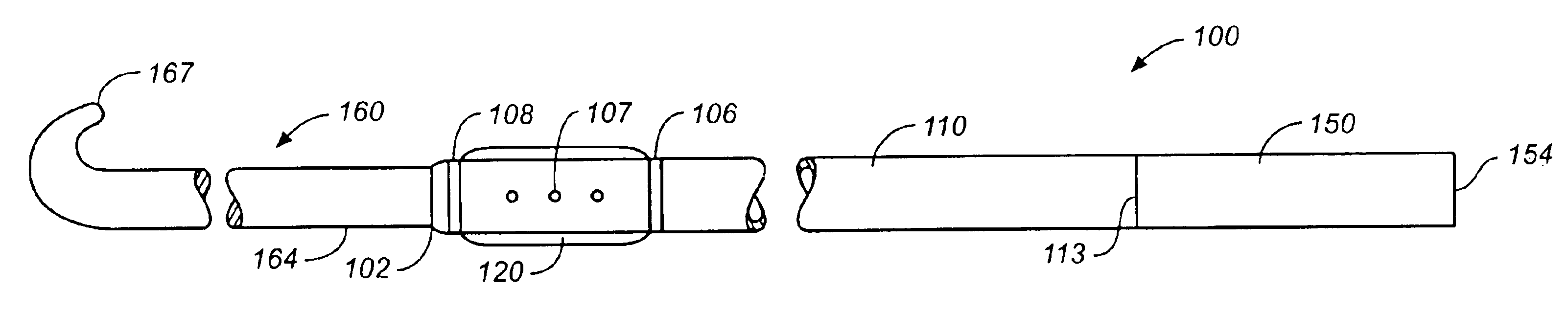
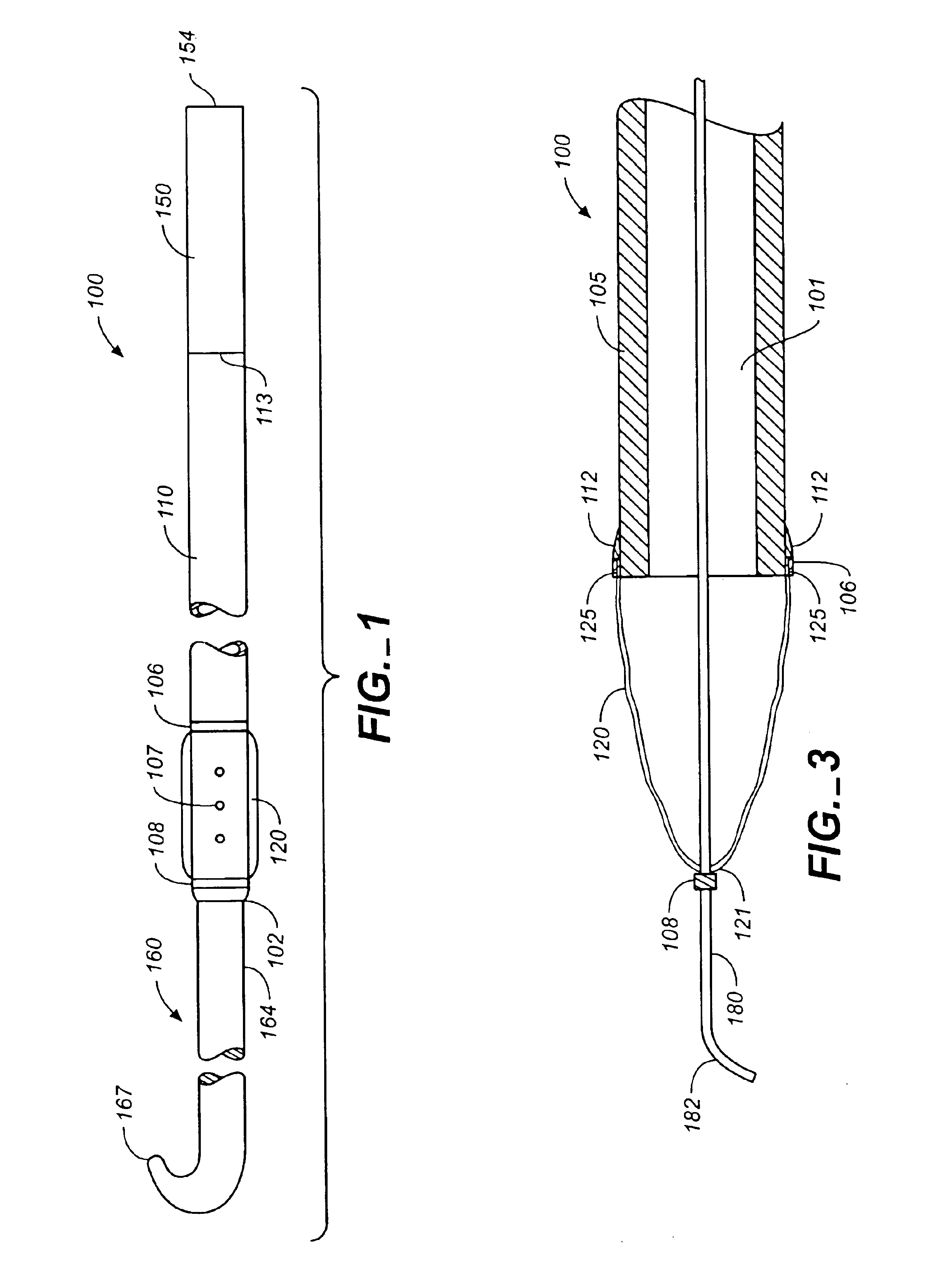
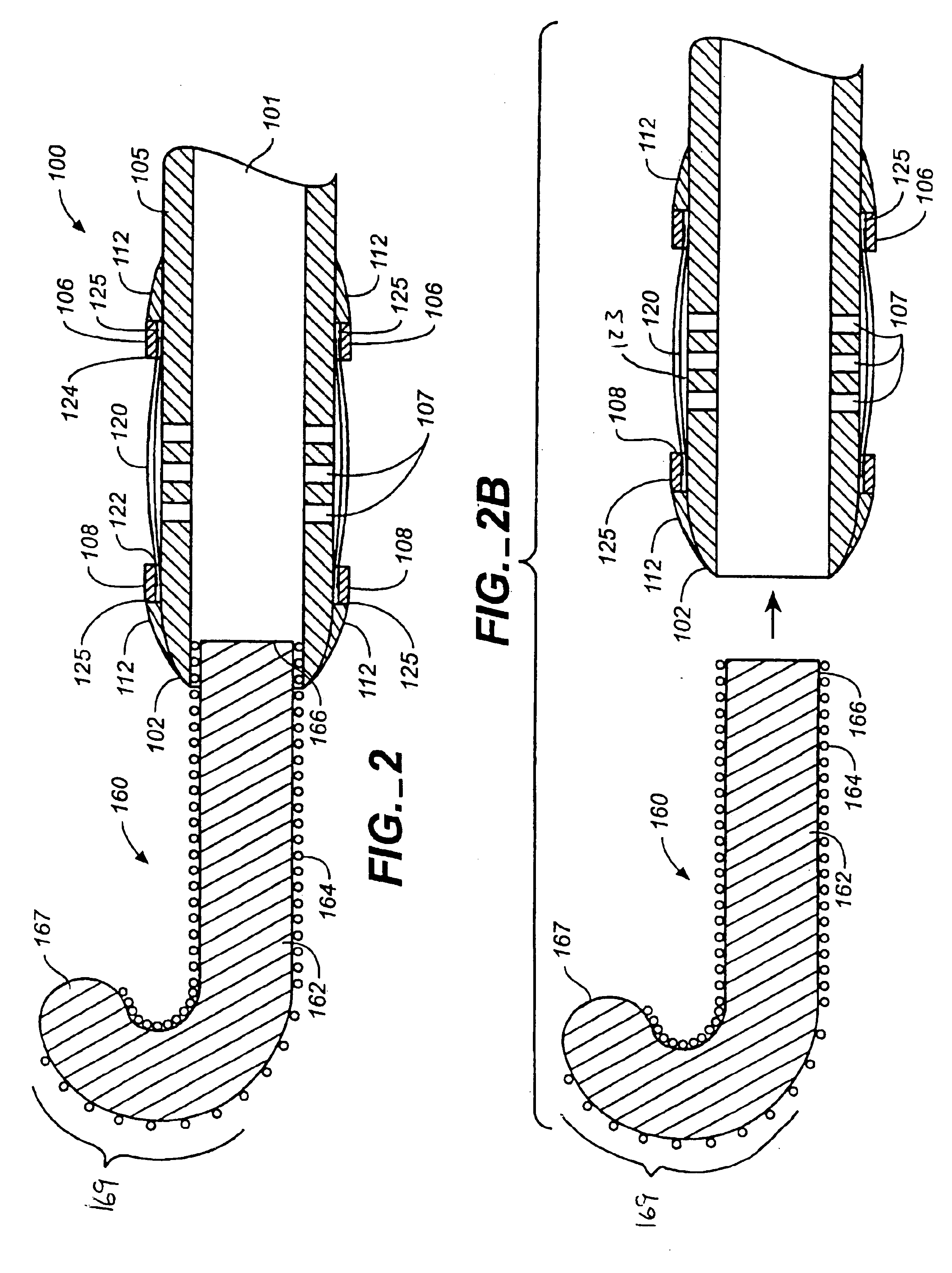
[0051]In accordance with the present invention there is shown and described a medical device for vessel occlusion. The medical device includes an elongated body having a distal end portion, a proximal end portion, and a lumen disposed therethrough. A balloon is disposed at the distal end portion of the elongated body, the balloon being in fluid communication with the lumen. An opening is defined at the proximal end portion of the elongated body, the opening being in fluid communication with the balloon via the lumen. A valve is disposed at the proximal end portion of the elongated body, the valve including a valve body movable between a closed position and an open position. The valve body is configured to engage a surface of the elongated body, distal to the opening, to seal the opening when the valve body is in the closed position.

[0052]Referring now to FIGS. 1, 2, and 11, there is shown a representative embodiment of a medical device 100 according to the present invention. The med...


PUM


Abstract

A medical device for vessel occlusion, the medical device including an elongated body having a distal end portion, a proximal end portion, and a lumen disposed therethrough, an balloon disposed at the distal end portion of the elongated body, the balloon in fluid communication with the lumen. An opening defined at the proximal end portion of the elongated body, the opening being in fluid communication with the balloon via the lumen, and a valve body moveably disposed at the proximal end portion of the elongated body, the valve body movable between a closed position and an open position, the valve body configured to engage a surface of the elongated body, distal to the opening, to seal the opening when the valve body is in the closed position.

Description

CLAIM OF PRIORITY[0001]The present application claims priority under 35 U.S.C. § 119 to U.S. Provisional Application Ser. No. 60 / 212,187 filed on Jun. 16, 2000, entitled “Angioplasty Catheter”, the entirety of which is incorporated by reference herewith.1. FIELD OF THE INVENTION[0002]The present invention relates to medical devices, specifically a medical device having a low profile valve for selectively inflating and deflating an inflatable balloon disposed upon the medical device, wherein the valve allows passage of interventional devices over the medical device during use.2. BACKGROUND OF THE INVENTION[0003]In order to perform many vascular procedures a guidewire is initially inserted into the patient's vasculature. The guidewire is generally inserted into the patient through an incision created in the patient's femoral artery. After the guidewire has been placed within the patient's vasculature, other interventional devices, such as catheters, maybe be passed over the guidewire....

Claims


Application Information

Patent Timeline
Patent Type & Authority Patents(United States)
IPC IPC(8): A61M25/10A61M25/00A61M39/00A61F2/958A61M25/08
CPCA61M25/1018A61M25/0069A61M25/007A61M25/0075A61M2025/1052A61M25/10185A61M25/104A61M39/06
Inventor CRAWFORD, LYNN D.BURDULIS, JR., ALBERTREYNOLDS, TIMSHUMER, DANEDMISTON, DARYLJOHNSON, STEVESCHLEGEL, KARRI
Owner ABBOTT LAB INC
Why Eureka
Try Eureka