Fuel supply for a fuel cell

a fuel cell and fuel supply technology, applied in the direction of rigid containers, machines/engines, liquid/fluent solid measurements, etc., can solve the problems of unsuitable dangerous or expensive fuel supplies for portable devices, danger to users, and inability to meet the requirements of fuel cell life, so as to reduce the volume of waste storage area and reduce the volume of fuel storage area

Inactive Publication Date: 2005-08-02
INTELLIGENT ENERGY LTD
View PDF16 Cites 118 Cited by
  • Summary
  • Abstract
  • Description
  • Claims
  • Application Information

AI Technical Summary

Benefits of technology

[0005]The present invention concerns a fuel supply for a fuel cell. The fuel supply includes a fuel storage area, a fuel solution outlet configured to pass fuel from the fuel storage area, a waste storage area, a waste inlet configured to pass waste into the waste storage area, and a movable barrier sepa

Problems solved by technology

Therefore, the life of the fuel cell is theoretically unlimited, requiring only that the fuel supply be periodically replenished.
While fuel cells may offer advantages over batteries for use with portable electronics, they may also present some problems.
Finally, some fuel supplies may be unsuitably dan

Method used


Image

  • Fuel supply for a fuel cell
  • Fuel supply for a fuel cell
  • Fuel supply for a fuel cell

Examples


second embodiment

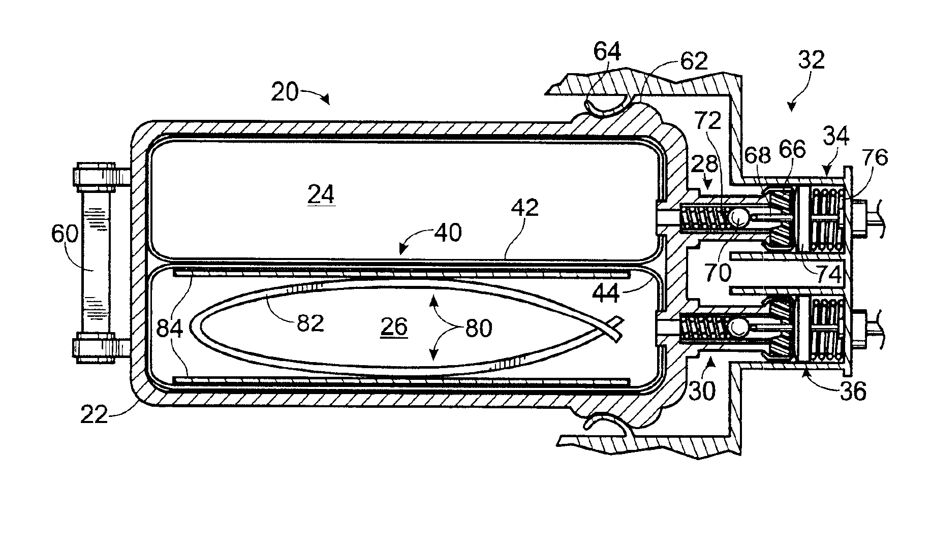
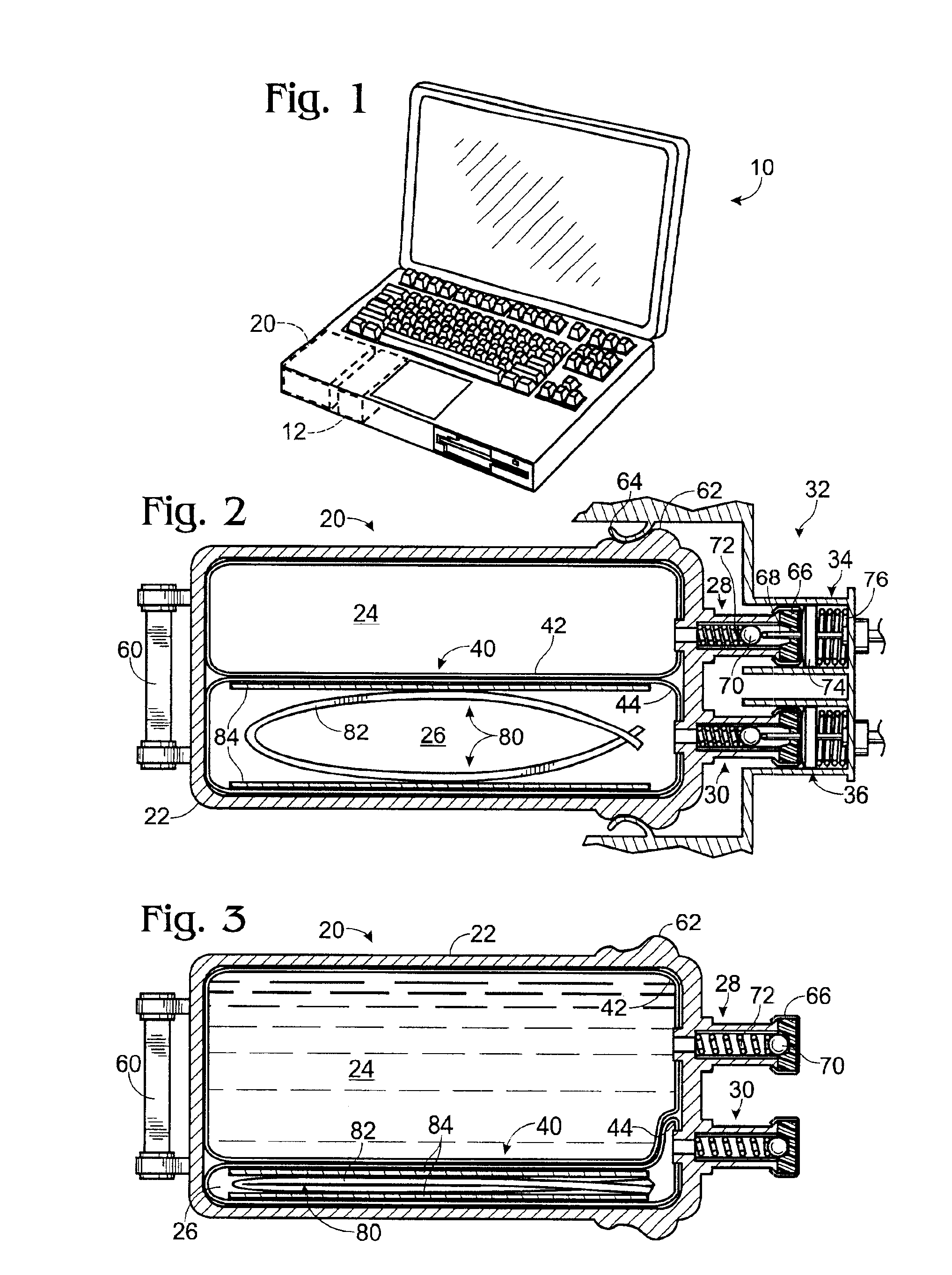
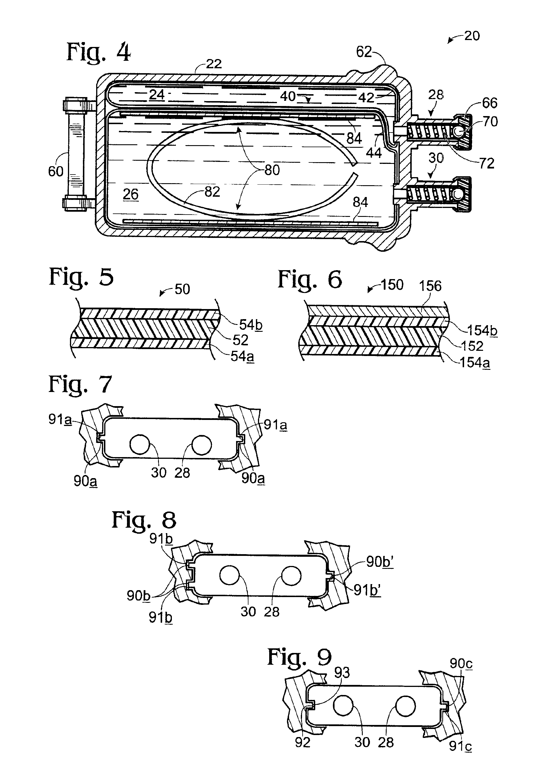
[0050]FIGS. 10-11 show generally at 120 a fuel supply according to the present invention. Fuel supply 120 is similar to fuel supply 20 described above, and may include any or all of the features described for fuel supply 20. For example, fuel supply 120 includes an outer container 122, and a fuel storage area 124 and waste storage area 126 contained within outer container 122. Fuel storage area 124 is bounded by a first flexible inner container 142, and waste storage area 136 is bounded by a second flexible inner container 144. Fuel supply 120 also includes a fuel inlet 128 configured to pass fuel from fuel storage area 124 to a fuel cell, and a waste inlet 130 configured to accept waste from the fuel cell and / or the catalyst.

[0051]In the embodiment of FIGS. 10-11, however, first flexible inner container 142 is positioned within the interior of second flexible inner container 144, rather than in a side-by-side arrangement. Thus, as waste flows into waste storage area 126, the waste ...

third embodiment

[0053]FIG. 12 shows generally at 220 a fuel supply according to the present invention. Fuel supply 220 includes an outer container 222 enclosing a fuel storage area 224 and a waste storage area 226, a fuel solution outlet 228 configured to pass fuel out of the fuel storage area, and a waste inlet 230 configured to pass waste into the waste storage area. Furthermore, fuel supply 220 includes a flexible inner container 242 that bounds fuel supply area 224. However, in the embodiment of FIG. 12, waste storage area 226 is not enclosed by a separate flexible inner container. Instead, the outer boundary of waste storage area 226 is defined by the inner wall of outer container 222. In this embodiment, fuel storage area 224 is completely surrounded by waste storage area 226, allowing for the efficient transfer of heat from the waste solution to the fuel solution. Furthermore, the waste solution will exert pressure on flexible inner container 242, thus pressurizing fuel storage area 224 rela...

fourth embodiment

[0054]A fuel supply according to the present invention may also be configured to supply hydrogen gas to a fuel cell, rather than a fuel solution. FIG. 13 shows generally at 320 a schematic depiction of fourth embodiment of a fuel supply according to the present invention. As with the previously described embodiments, fuel supply 320 includes an outer container 322 enclosing a fuel storage area 324 and a waste storage area 326. Furthermore, fuel storage area 324 is bounded by a first inner container 328, and waste storage area 326 is bounded by a second inner container 330.

[0055]Unlike the previously described embodiments, however, fuel supply 320 also includes a catalyst 340 to produce hydrogen gas from the fuel solution. Fuel solution from fuel storage area 324 is fed to a catalyst 340 via a pump 342. Catalyst 340 catalyzes the conversion of the borohydride in the fuel solution to hydrogen gas and borate waste in the presence of water (or other suitable oxygen source). Any suitable...


PUM


Abstract

The present invention concerns a fuel supply for a fuel cell. The fuel supply includes a fuel storage area configured to hold a fuel solution, a fuel solution outlet configured to pass the fuel solution from the fuel storage area, a waste storage area, a waste inlet configured to pass waste into the waste storage area, and a movable barrier separating the fuel storage area and the waste storage area. The movable barrier is configured to move as fuel solution is passed from the fuel storage area and waste solution is passed into the waste storage area to simultaneously decrease the volume of the fuel storage area and increase the volume of the waste storage area.

Description

TECHNICAL FIELD[0001]The present invention relates to a fuel supply for a fuel cell. More particularly, the invention concerns a fuel supply having a fuel storage area and a waste storage area separated by a movable barrier.BACKGROUND OF THE INVENTION[0002]Fuel cells in general, and hydrogen fuel cells in particular, have received increased interest as possible power supplies for portable electronic devices. A fuel cell is an electrochemical device for continuously converting chemicals into direct-current electricity. A fuel cell typically includes two electrically conducting electrodes separated by an ionic-conducting electrolyte, and also any necessary systems for moving fuel into the cell or waste out of the cell. Fuel is continuously fed to one of the electrodes, where it is converted to an intermediate and travels through the electrolyte. A chemical that reacts with the fuel intermediate is fed to the other electrode. In a hydrogen fuel cell, hydrogen is fed to the anode, and o...

Claims


Application Information

Patent Timeline
IPC IPC(8): F02M37/00H01M8/04H01M8/06B01J7/02C01B3/06G06F1/26
CPCB01J7/02C01B3/065G06F1/26H01M8/04186H01M8/04208H01M8/0662H01M2250/30Y02E60/362Y02T10/16Y02E60/50Y02B90/18F17C11/005Y02B90/10Y02E60/36Y02T10/12
Inventor PRASAD, RAVILIU, QINJOHNSON, LOREN E.BULLOCK, MICHAEL L.CHILDERS, WINTHROP D.MANN, L. CHRISTSANG, JOSEPH W.
Owner INTELLIGENT ENERGY LTD
Why Eureka
Try Eureka