Method and unit for controlling the flow of a TCP connection on a flow controlled network

a flow control and flow control technology, applied in data switching networks, frequency-division multiplexes, instruments, etc., can solve the problems of affecting the performance of the protocol, the different tcp connections are unfairly distributed, and the connection using a small size or being subjected to longer transmission times occupies the resources available in the network less quickly, so as to achieve the effect of convenient implementation

Inactive Publication Date: 2005-08-02
MITSUBISHI ELECTRIC CORP
View PDF11 Cites 139 Cited by
  • Summary
  • Abstract
  • Description
  • Claims
  • Application Information

AI Technical Summary

Benefits of technology

[0025]The objective of the invention is to propose an alternative to the known methods of flow control on a TCP connection, in particular a connection established across a flow controlled network, which is simpler and therefore easier to implement.

Problems solved by technology

From the of view of the sender, the duplicated acknowledgements may be attributed to various problems on the network: the fact that the network has re-arranged the segments, that it has duplicated acknowledgements or finally that segment has been lost.
Although very robust, the TCP flow control and congestion mechanisms may lead to a deterioration in performance of the protocol.
Conversely, a connection using segments of a small size or which is subjected to longer transmission times occupies the resources available in the network less quickly.
This results in an unfair distribution between the different TCP connections, transmission rate resources and network memory.
Secondly, the end-to-end transmission time is poorly controlled.
In effect, since no network resources have been allocated to the connection in advance and TCP does not work on the basis of explicit information about the status of the network, congestion points can arise, characterised by uncontrolled transfer times of traffic queues.
Furthermore, the mechanism of detecting losses on the basis of expired retransmission time-outs and the retransmission of lost segments also has an uncontrolled effect in terms of transmission times. Thirdly, congestion is not detected until late on, precisely due to the implicit nature of this detection system, based as it is on detecting the loss of a segment.
As a result, it is not possible to avoid the loss of segments and hence their retransmission.
Fourthly, and this drawback results from the latter, the effective transmission rate is ineffectively used since the transmission rate and memory resources are used not only to transport the lost segments as far as the congestion point but also to retransmit them.
Typically, until it reaches its maximum window size, TCP occupies an increasing amount of transmission rate and memory resources until they become saturated.
The memory capacity offered by the path is very limited (assuming a reasonable transmission rate and propagation time) and depends on the passband-transfer product.
They may therefore occupy a memory space of up to several tens of kilobytes per connection (depending on the version of TCP used) and therefore risk causing congestion.

Method used


Image

  • Method and unit for controlling the flow of a TCP connection on a flow controlled network
  • Method and unit for controlling the flow of a TCP connection on a flow controlled network
  • Method and unit for controlling the flow of a TCP connection on a flow controlled network

Examples


Embodiment Construction

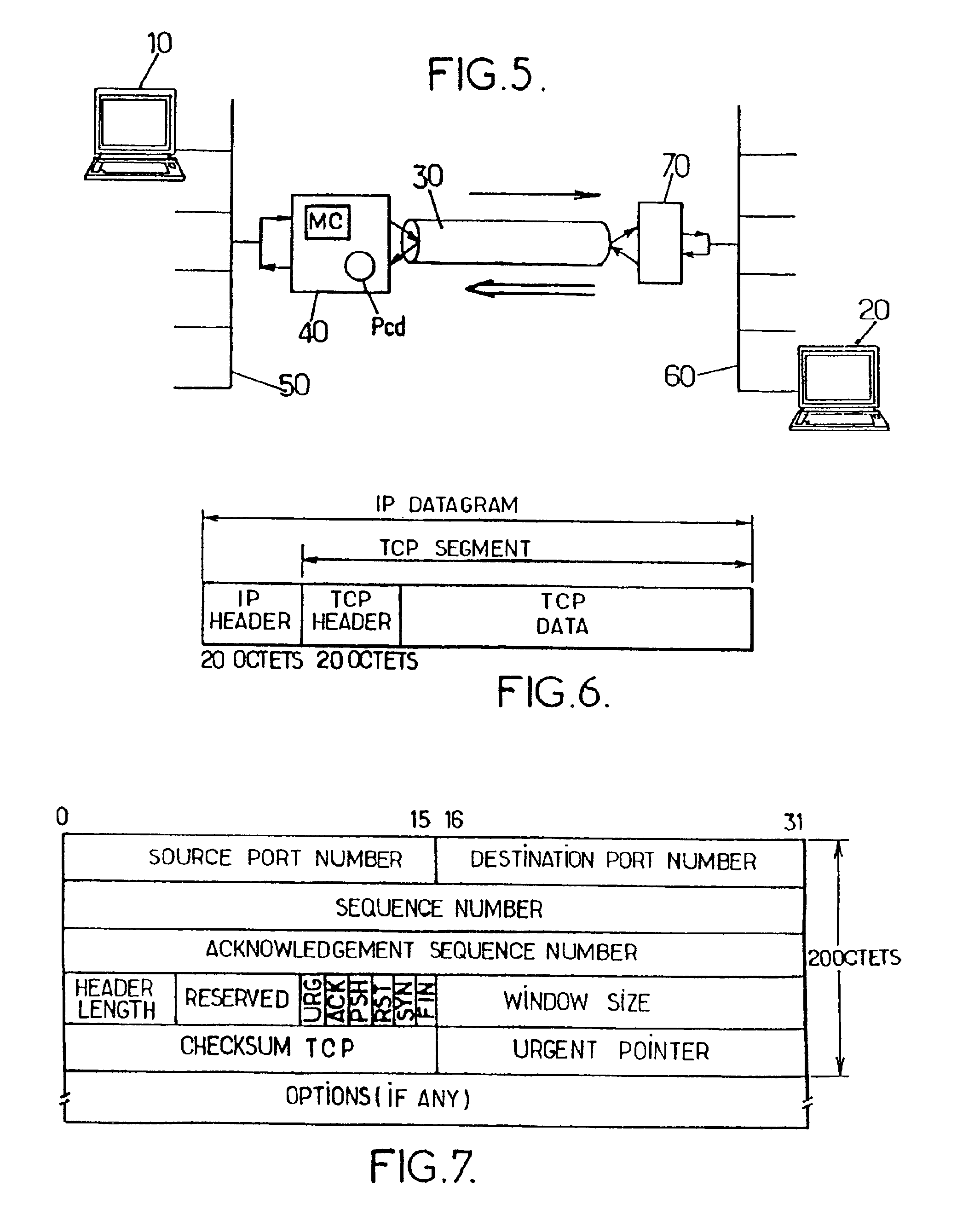
[0047]FIG. 5 schematically illustrates an example of a TCP link on a flow controlled network adapted to implementation of the method proposed by the invention. The example relates to an application programme being run on a computer 10 (hereafter sender) which has to transmit data to an application programme being run on a remote computer 20 (hereafter receiver). These two application programmes use the TCP protocol to communicate. The sender 10 is connected to a local network 50, for example a high speed Ethernet network. A network of this type does not generate congestion because of the high speed available relative to the volume of data which it transmits. The receiver 20 is also connected to a local network 60. In one example, the local area network 60 is also assumed to be an Ethernet network but, of course, it may also be a different network, of the LAN type (Local Area Network), for example.

[0048]The TCP connection is made on a flow controlled network 30, for example an ATM ne...


PUM


Abstract

The invention proposes a method and a unit for controlling the flow of at least one TCP connection between a sender and a receiver. The method is of the type which consists in controlling, at the level of a given multiplexing node through which TCP segments relevant to the connection pass, a window size parameter contained in acknowledgement segments sent back by the receiver. The method comprises the steps of:
    • a) receiving an acknowledgement from the receiver on the up link (receiver to sender) of the connection at the level of said given multiplexing node;
    • b) controlling a window size parameter contained in, said acknowledgement segment on the basis of the difference between, firstly, a first context value associated with the TCP connection, defined as being the sequence number of the last segment that was transmitted from said given multiplexing node on the down link (sender to receiver) of the connection, to which the length of said segment is added, and, secondly, the sequence number indicated in said acknowledgement segment;
    • c) transmitting the acknowledgement segment to the sender the up link of the connection from said multiplexing node with the window size parameter thus controlled.

Description

TECHNICAL FIELD[0001]The present invention relates to a method and a unit for controlling the flow of a TCP connection, in particular a TCP connection established across a flow controlled network.BACKGROUND OF THE INVENTION[0002]The TCP protocol (Transmission Control Protocol), referred to hereafter as TCP, is a protocol of the transport layer in the TCP / IP layer. It is very widely used in networks and most widely used on the Internet network. It provides a transport service for application programmes in the upper layer in the form of two-way communications carrying a flow of octets between a sender and a receiver on which these programmes are run (this is known as end-to-end transmission). For example, the sender and the receiver may be a network server and a client final respectively. Some of the protocols supported by TCP are: FTP (File Transfer Protocol) used to transmit files, HTTP (Hyper Text Transfer Protocol) which handles transactions on the Internet network or SMTP (Simple...

Claims


Application Information

Patent Timeline
Patent Type & Authority Patents(United States)
IPC IPC(8): H04L1/16H04L1/18H04L29/06H04L1/00H04L29/08H04L12/56G06F13/00H04L12/70
CPCH04L1/1671H04L1/1809H04L1/1835H04L1/187H04L29/06H04L69/16H04L69/163H04L1/0001H04L1/1806H04L1/188H04L2012/5667H04L69/326H04L9/40
Inventor MANGIN, CHRISTOPHE
Owner MITSUBISHI ELECTRIC CORP
Why Eureka
Try Eureka