

System and method for increasing bandwidth efficiency and throughput of a data transmission network
- Summary
- Abstract
- Description
- Claims
- Application Information
AI Technical Summary
Benefits of technology
Problems solved by technology
Method used
Image

Examples
Embodiment Construction
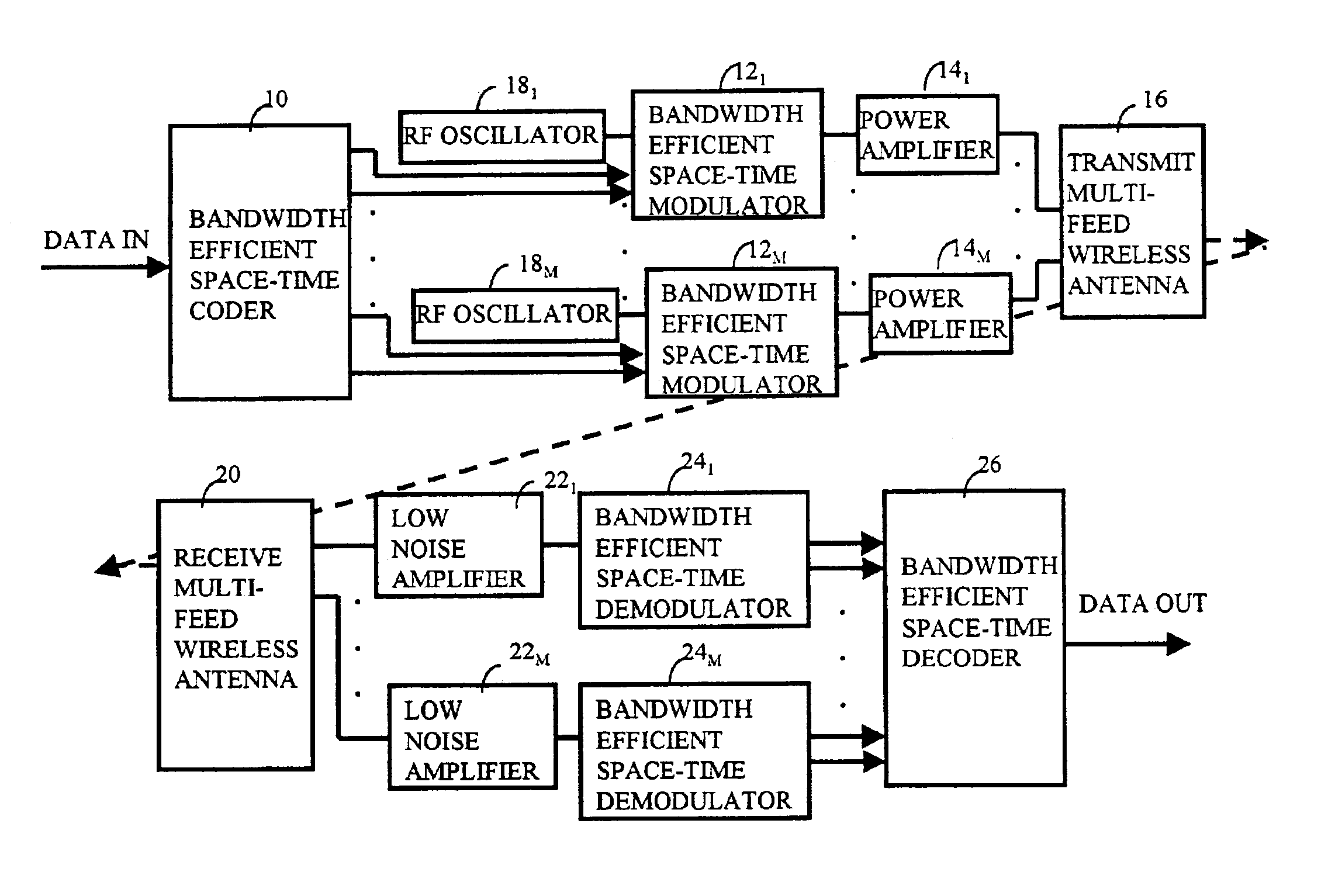
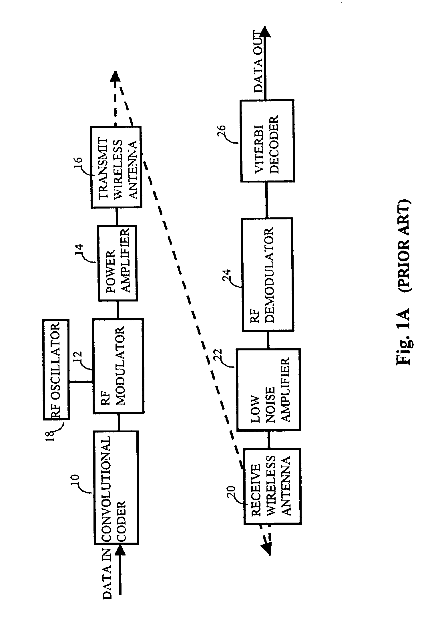
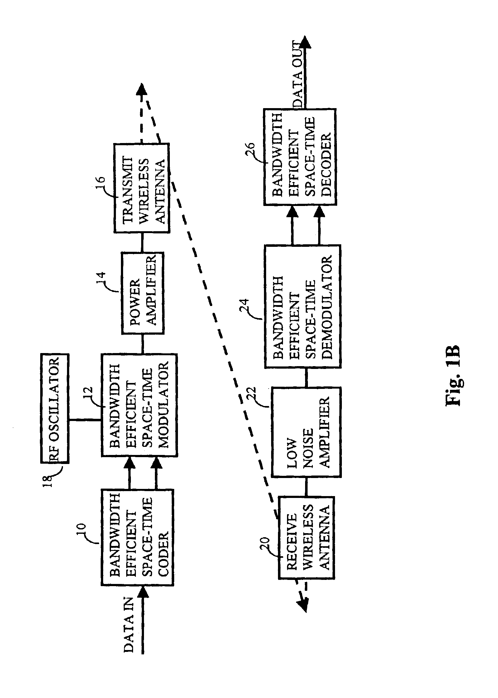
[0093]In accordance with the invention disclosed herein, channel capacity and data throughput of wireless, free-space optical, and fiber-optical communication links can be dramatically increased depending on the order of space-time modulation, transmission waveform, space-time error correction code, the number of spatial and temporal modes, as well as the size of the transmit and receive antenna array. For a typical wireless system generating a temporally coded and temporally modulated signal followed by a single-feed antenna transmitting to a single-feed antenna receiving system, the wireless link capacity, throughput and bit error rate performance is limited by the efficiency of the temporal modulation and effectiveness of the error correction code used. The present invention significantly increases the system throughput and performance of prior art by encoding data with a space-time error correction code, followed by space-time modulation using a bandwidth efficient waveform befo...
PUM
 Abstract
Description
Claims
Application Information