
Method and apparatus for transmission of upstream data in an optical network

a technology of optical network and transmission method, applied in the field of optical network, can solve the problems of significant network resource consumption, unsatisfactory and inefficient level of complexity, and transmission of upstream data

Inactive Publication Date: 2005-08-02
INTEL CORP
View PDF7 Cites 10 Cited by
  • Summary
  • Abstract
  • Description
  • Claims
  • Application Information

AI Technical Summary

Benefits of technology

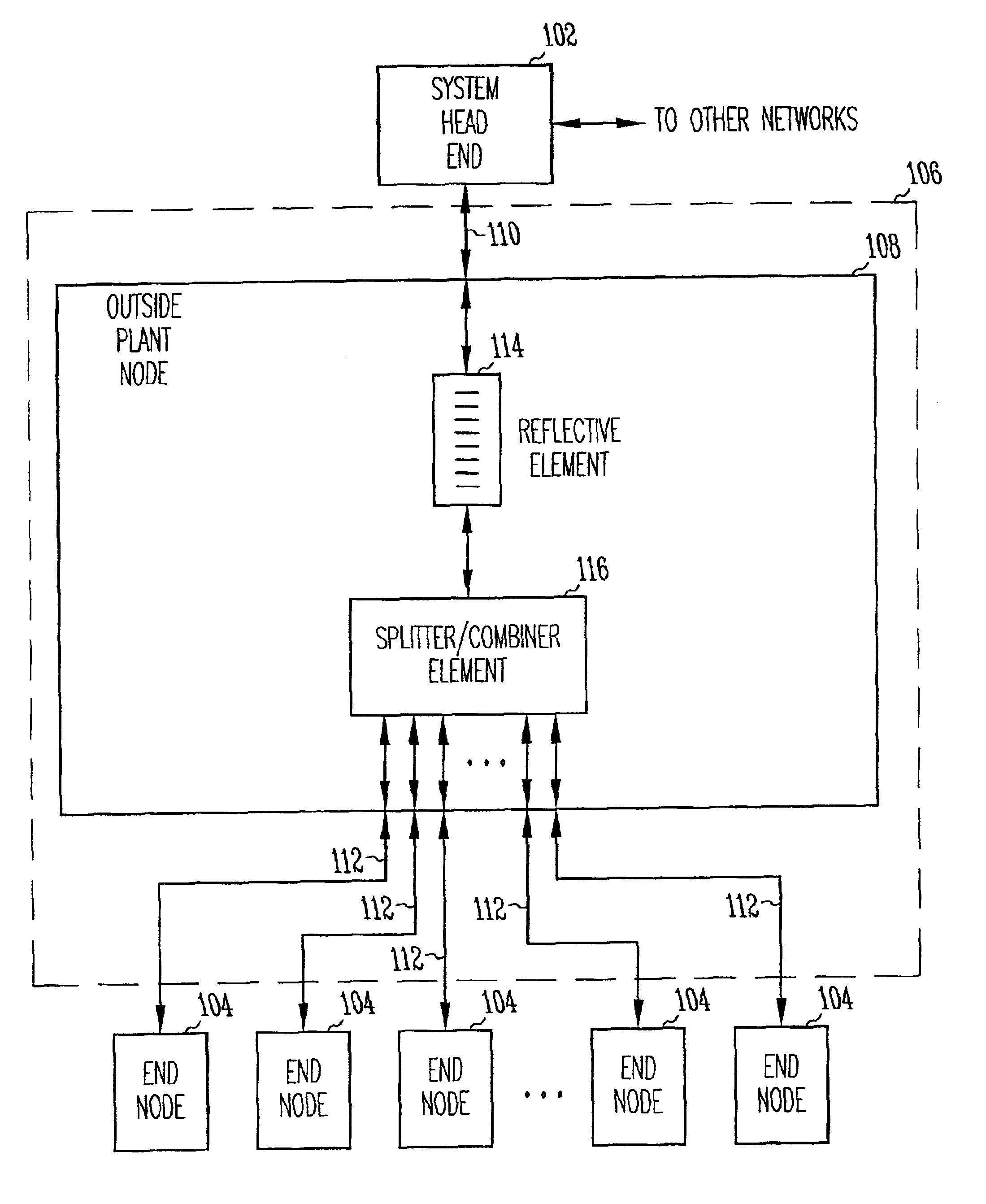
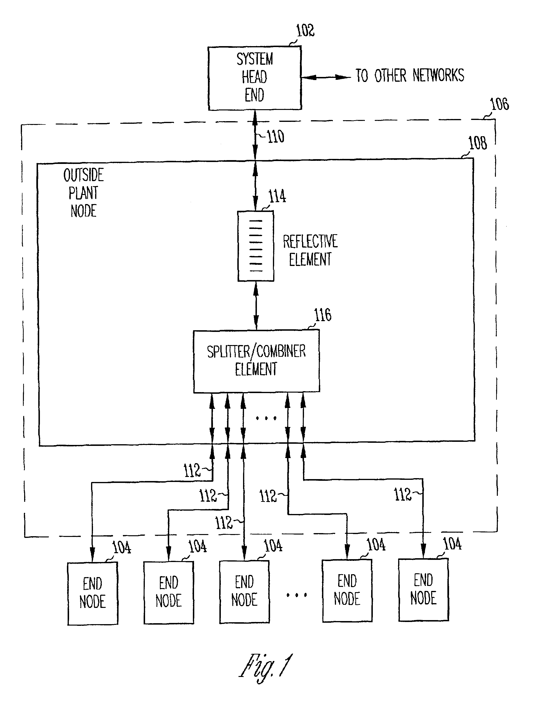
The present invention is about improving the transmission of upstream data in a Passive Optical Network (PON) by using a less complex and efficient technique. The current methods of transmitting upstream data are inefficient and consume significant network resources. The invention proposes a method and system for coordinating transmission of upstream data between the system head end and the remotely located end nodes, allowing for variable length upstream data frames to be sent by each end node without explicit size reservation message exchange by the system head end. The invention also allows for the efficient transmission of upstream data in a PON by eliminating transit delay wait periods and coordinating transmission of upstream data between remotely located end nodes and the system head end in a PON with centralized scheduling.

Problems solved by technology

Although the art of transmitting downstream data from a system head end to remotely located end nodes is well developed, there remain some problems with the transmission of the upstream data.
This level of complexity is undesirable and inefficient and consumes significant network resources.
This technique is highly inefficient because the system head end commands all end nodes to halt upstream transmissions and specifies a single end node for transmission.

Method used


Image

  • Method and apparatus for transmission of upstream data in an optical network
  • Method and apparatus for transmission of upstream data in an optical network
  • Method and apparatus for transmission of upstream data in an optical network

Examples


Embodiment Construction

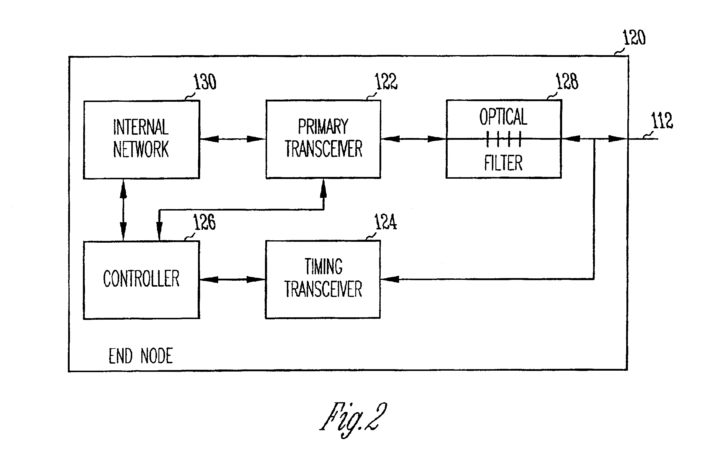
[0016]The present invention relates to optical networks. In accordance with one of the embodiments, remotely located end nodes transmit upstream data on a first wavelength through an optical network to a system head end followed by a timing signal on a second wavelength. The timing signals are reflected by a wavelength selective reflective element to each of the end nodes. The end nodes track the timing signals to determine when to transmit upstream data in accordance with a transmission sequencing schedule provided by the system head end. In accordance with this embodiment, the optical network includes an outside plant node coupled to the system head end with a distribution fiber. The outside plant node is coupled to the end nodes with drop fibers. The outside plant node may include an optical splitter / combiner element along with the wavelength selective reflective element.

[0017]In accordance with another embodiment, a method of coordinating transmission of upstream data between a ...


PUM


Abstract

In an optical network that communicates upstream data utilizing a time division multiple access (TDMA) technique, end nodes transmit upstream data on a first wavelength in accordance with a transmission sequence. The end nodes transmit a timing signal on a second wavelength following the upstream data. The timing signals are reflected by a wavelength selective reflective element to each of the end nodes. The end nodes track the timing signals to determine when to transmit upstream data in accordance with the transmission sequence. The optical network includes an outside plant node coupled to the system head end with a distribution fiber. The outside plant node is coupled to the end nodes with drop fibers. The outside plant node includes a splitter / combiner and the wavelength selective reflective element. The wavelength selective reflective element reflects the timing signals on the second wavelength and passes upstream and downstream data on other wavelengths.

Description

FIELD OF THE INVENTION[0001]The present invention pertains to optical networks, and in particular, to passive optical networks (PONs) that provide for transmission and reception of upstream and downstream data between a system controller and a plurality of optical network units (ONUs), and more particularly to PONs that utilize time division multiple access (TDMA) techniques for the upstream data transmissions.BACKGROUND OF THE INVENTION[0002]The desire to have broadband information services available at residential customer premises has promoted intense interest in the use of optical fiber media. Fiber-to-the-home, in which optical fiber transport is used over the entire path, is appealing because of the large information capacity of optical fiber. Various techniques for communicating over optical fiber include time division multiplexing (TDM) techniques, wavelength division multiplexing (WDM) techniques, sub-carrier multiplexing (SCM) techniques, and spatial division multiplexing ...

Claims


Application Information

Patent Timeline
Patent Type & Authority Patents(United States)
IPC IPC(8): H04J14/02H04J3/16H04B10/207H04Q11/00H04J3/06H04B10/27H04J3/00H04B10/272H04J14/00
CPCH04J3/0655H04J14/0226H04J14/0282H04Q11/0062H04J14/0232H04J14/0238H04J14/0246H04J14/0247H04J14/025H04J14/0252H04Q11/0067H04Q2011/0064H04Q2011/0086H04Q2011/0088
Inventor HORNE, DAVID M.
Owner INTEL CORP
Learn More