Electric steering apparatus

a technology of electric steering and steering shaft, which is applied in the direction of trailer steering, mechanical energy handling, transportation and packaging, etc., can solve the problems of affecting the smoothness of steering, the inability to obtain smooth steering feeling, and the loss of smooth steering feeling, so as to reduce the rigidity of the rotational shaft and increase the size of the electric motor.

a technology of electric steering and steering shaft, which is applied in the direction of trailer steering, mechanical energy handling, transportation and packaging, etc., can solve the problems of affecting the smoothness of steering, the inability to obtain smooth steering feeling, and the loss of smooth steering feeling, so as to reduce the rigidity of the rotational shaft and increase the size of the electric motor.

US6926299B2Inactive Publication Date: 2005-08-09HONDA MOTOR CO LTD

Image

  • Electric steering apparatus
  • Electric steering apparatus
  • Electric steering apparatus

Examples


Embodiment Construction

[0020]With reference to the accompanying drawings, an electric steering apparatus according to the present invention will be described in detail.

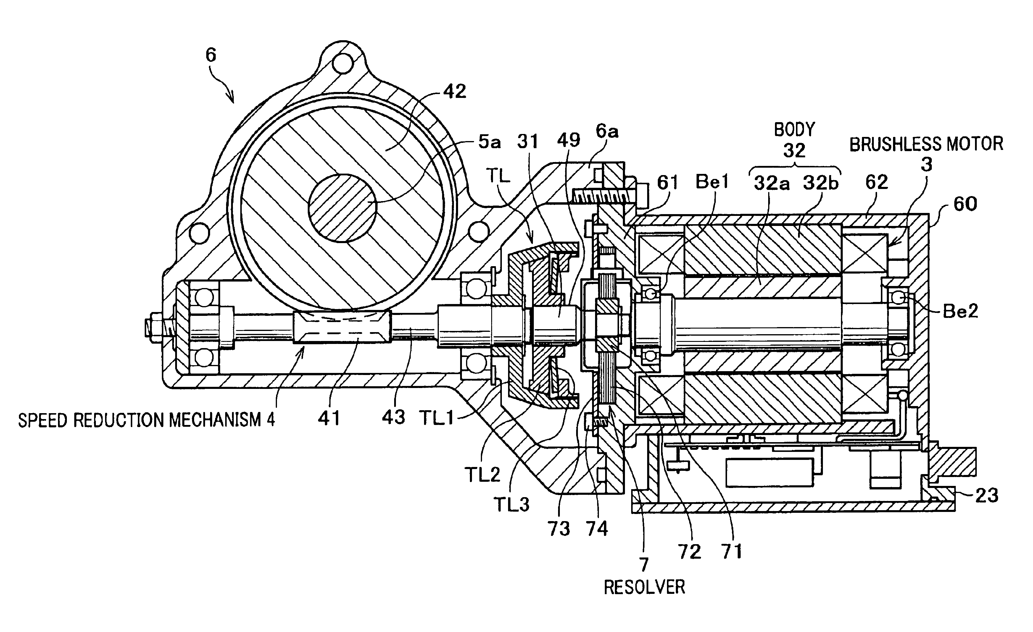
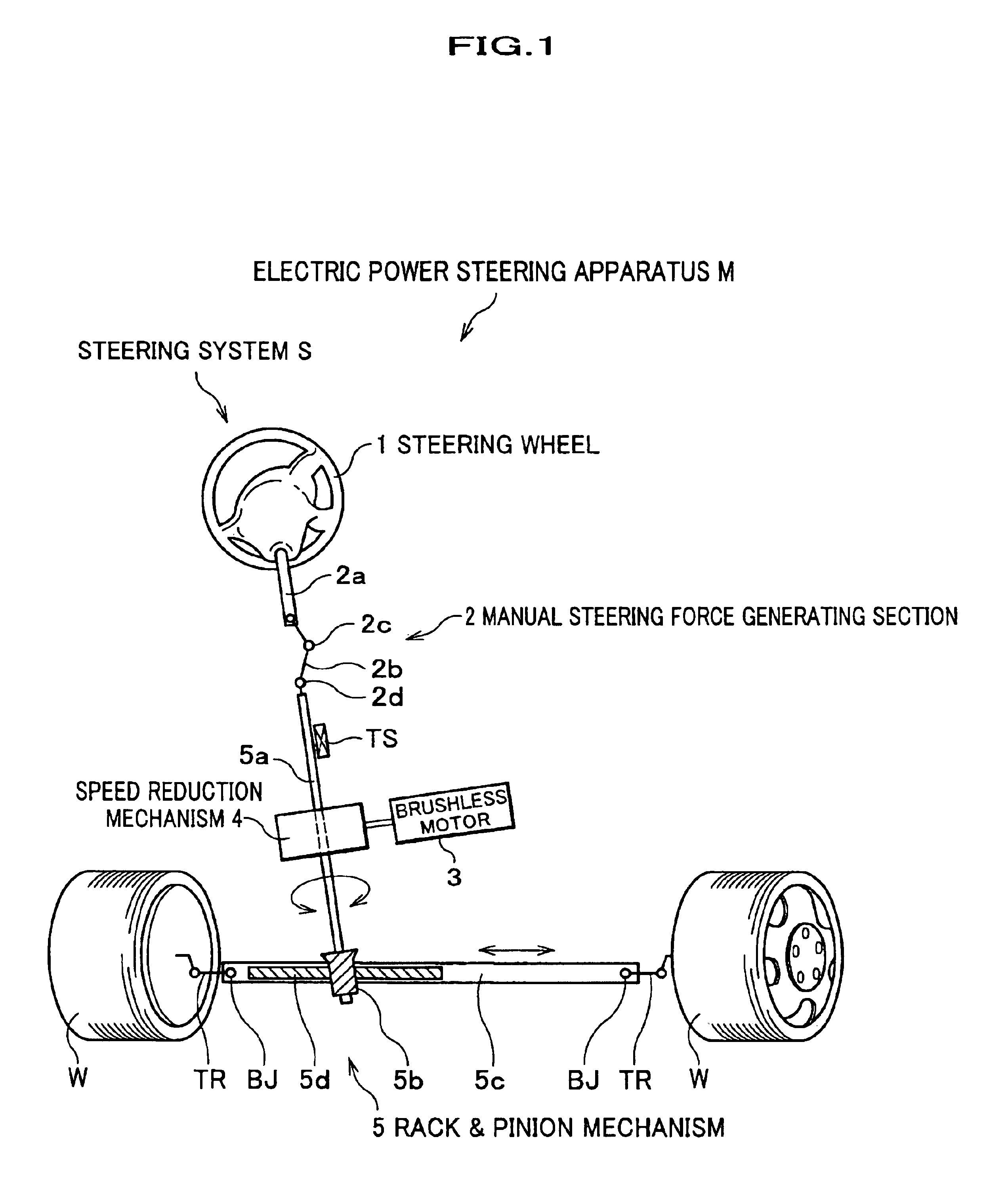
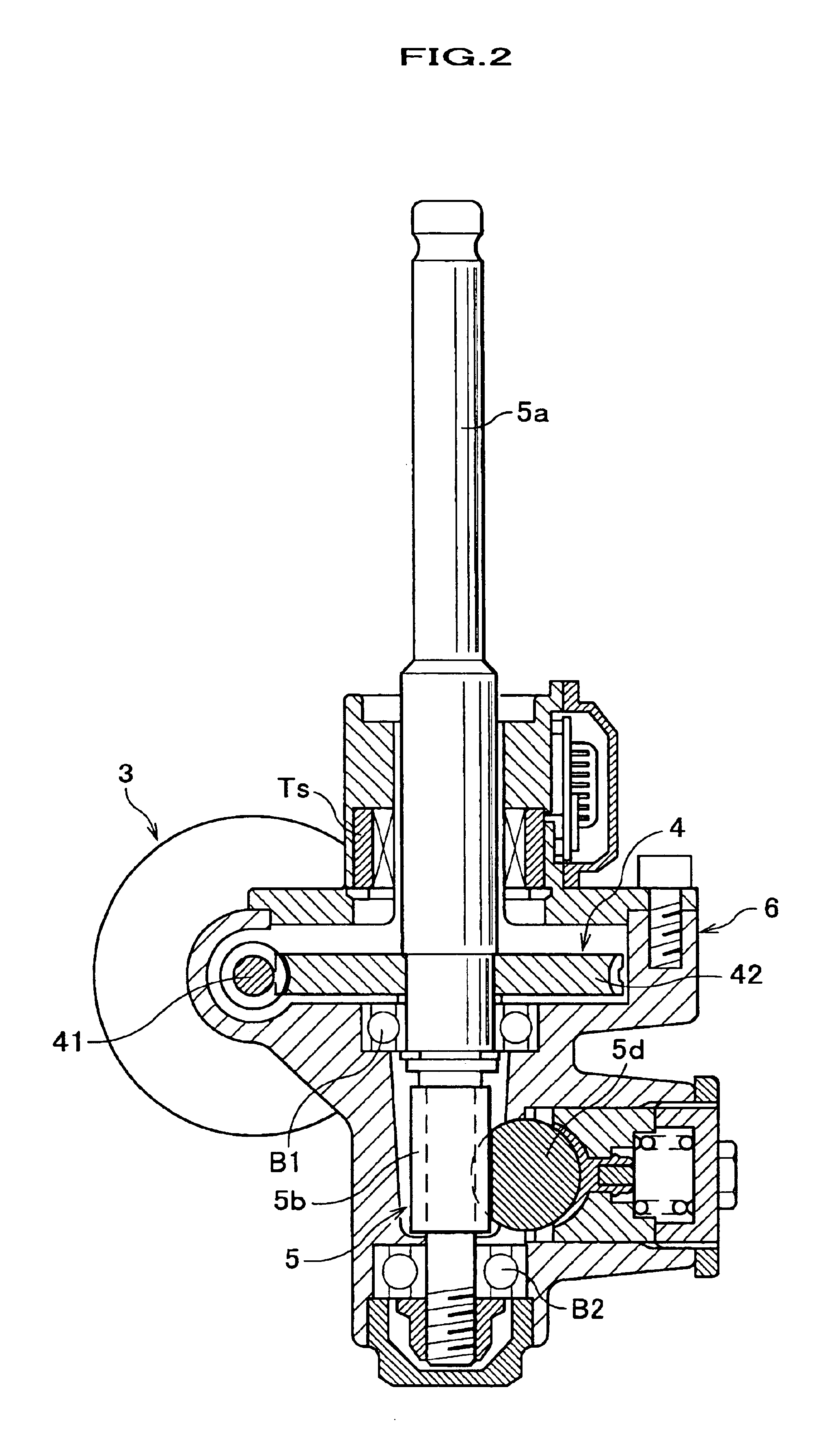
[0021]As shown in FIG. 1, an electric power steering apparatus (electric steering apparatus) M is arranged in a steering system S extending from a steering wheel 1 to steerable wheels W, W. The electric power steering apparatus M assists a steering force generated by a manual steering force generating section 2. To be more specific, the electric power steering apparatus M drives a brushless motor (electric motor) 3 to generate assist torque (assist steering force) which is then increased at a speed reduction mechanism 4 with a speed reduction and transmitted to the pinion shaft 5a, so that the manual steering force at the manual steering force generating section 2 can be eased. The electric power steering apparatus M is further provided with a controller (not shown) which controls the brushless motor 3 in accordance with the steering manipu...


PUM


Abstract

An electric steering apparatus includes a brushless motor 3 which applies torque to a steering system through a speed reduction mechanism 4, and a resolver 7 which detects a rotation angle of the output shaft 31 of the brushless motor 3. The resolver 7 is arranged between the brushless motor 3 and the speed reduction mechanism 4 in a manner separately from the body 32 of the brushless motor 3.

Description

BACKGROUND OF THE INVENTION[0001]The present invention relates to an electric steering apparatus which includes an electric motor for applying torque to a steering system through a speed reduction mechanism, and a rotation detector for detecting a rotation angle of the rotational shaft of the electric motor.[0002]Electric power steering apparatus for assisting the driver's steering operation is known as an electric steering apparatus which applies a driving force of the electric motor to the steering shaft through the speed reduction mechanism. As shown in FIG. 4, Japanese Laid-open Patent Application No. 2002-331946 (paragraph numbers 0032 and 0033, FIG. 4) discloses such an electric power steering apparatus with a brushless motor 100.[0003]In this electric power steering apparatus 200 using the brushless motor 100, a drawback in the brushless motor 100, such as voltage drop between brush and commutator due to wear of the brush by repeated use over extended time period, can be over...

Claims


Application Information

Patent Timeline
09 Aug 2005
Publication
US6926299B2
IPC
B62D5/04; H02K7/10; H02K29/06; H02K7/116; H02K7/108; H02K11/00
CPC
B62D5/0403; H02K7/108; H02K7/1166; H02K11/0031; H02K11/0042; H02K29/06; H02K11/225; H02K11/24
Inventors
YONEDA, ATSUHIKO; SHIMIZU, YASUO