Transmission module assembly having printed circuit board

Active Publication Date: 2005-08-09
HON HAI PRECISION IND CO LTD
View PDF7 Cites 22 Cited by
  • Summary
  • Abstract
  • Description
  • Claims
  • Application Information

AI Technical Summary

Benefits of technology

[0011]Accordingly, a first object of the present invention is to provide a transmission module assembly having an electr

Problems solved by technology

It is obvious that employing the cover to position the printed circuit board and urge an electrical engagement between the printed circuit board and the contact elements complicates the assembling process and increases the manufacturing cost.
Accordingly, the assembling process is complicated and

Method used


Image

  • Transmission module assembly having printed circuit board
  • Transmission module assembly having printed circuit board
  • Transmission module assembly having printed circuit board

Examples


Embodiment Construction

[0025]Reference will now be made in detail to the preferred embodiment of the present invention.

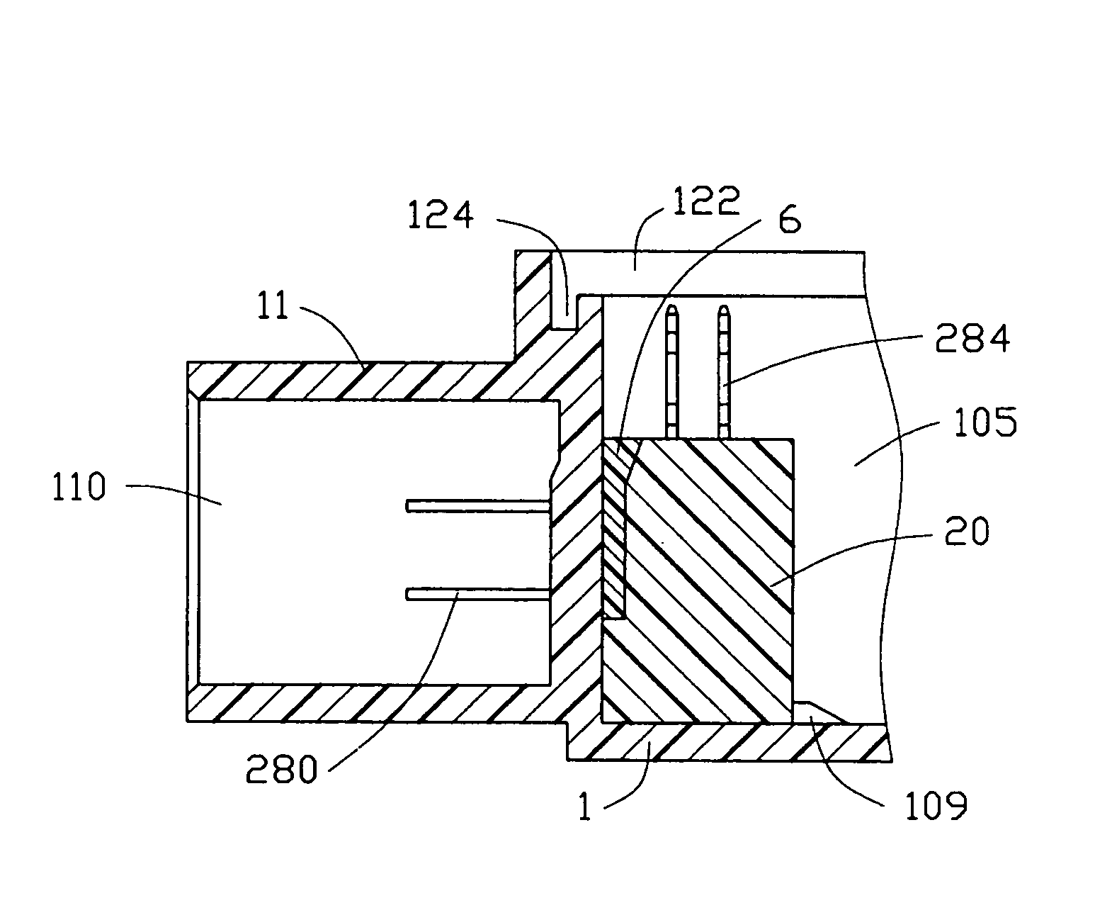
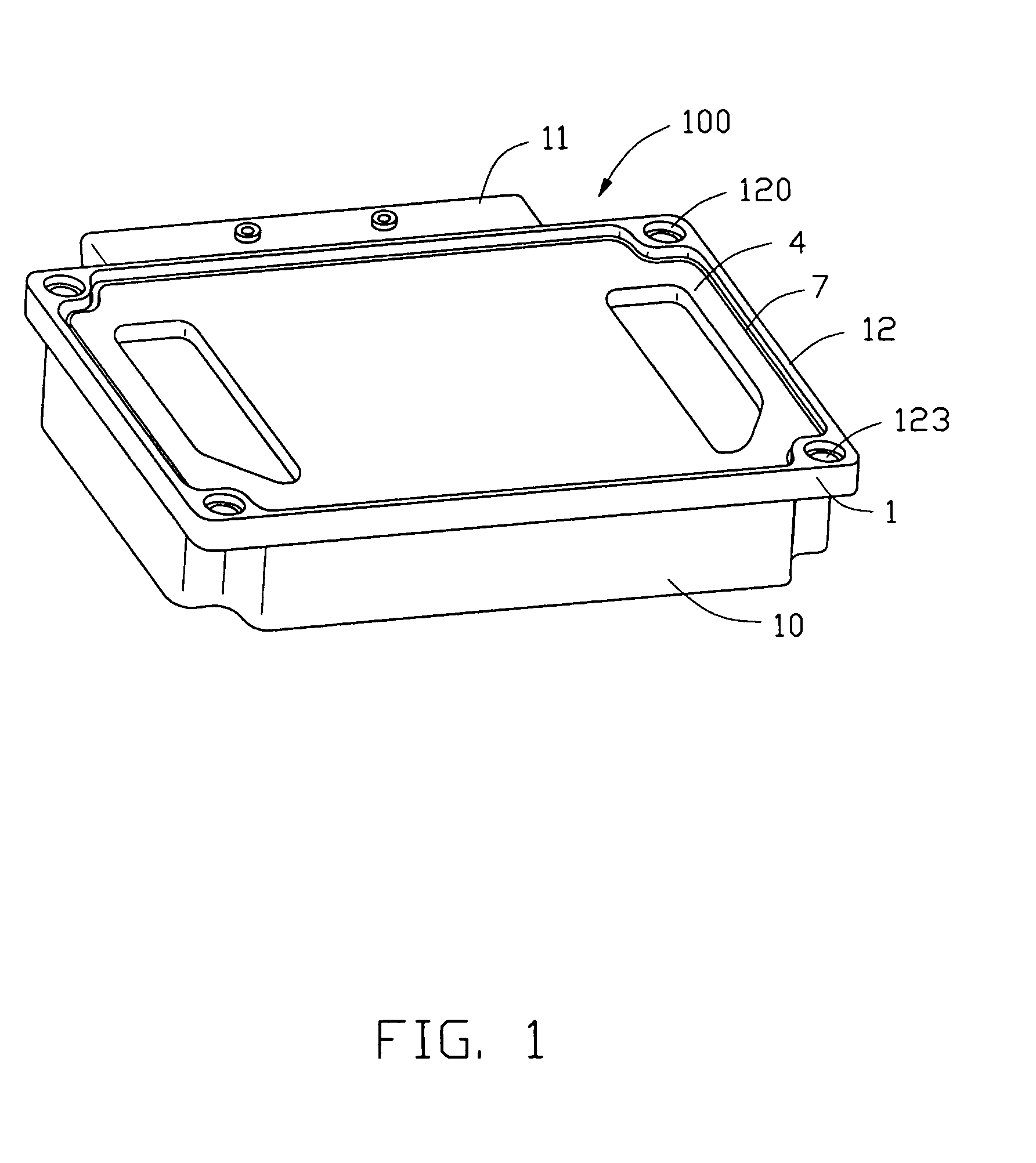
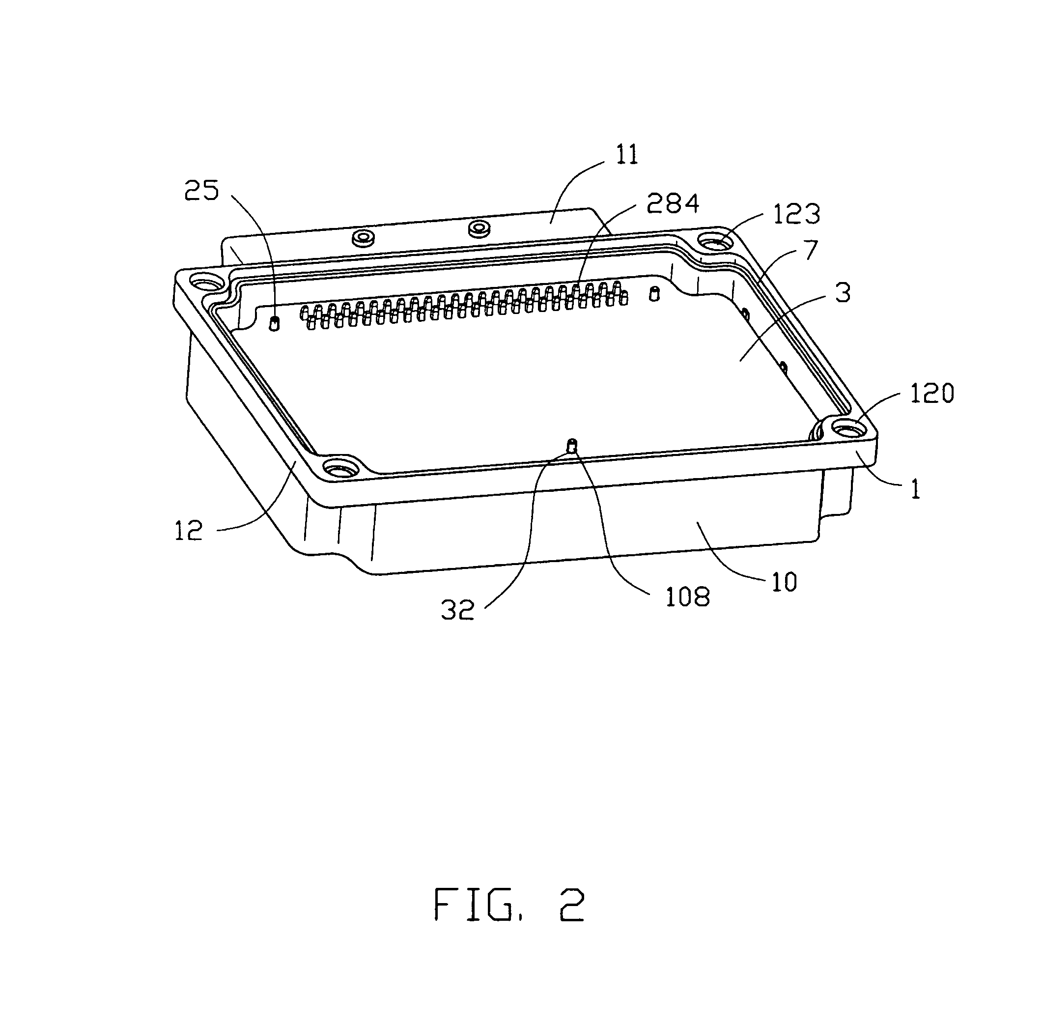
[0026]Referring to FIGS. 1, 2 and 3, a transmission module assembly 100 in accordance with the present invention comprises a module cover 1, an electrical connector 2 received in the module cover 1, a printed circuit board 3 installed into the module cover 1 to have an electrical connection with the electrical connector 2, and a cover member 4 assembled to the module cover 1 to protect the printed circuit board 3.

[0027]Referring to FIGS. 5 and 6, the module cover 1 includes a body 10, a mating portion 11 and a flange 12. The body 10 has a bottom wall 101, a front and a rear walls 102, 103 respectively extending upwardly from front and rear edges of the bottom wall 101, and a pair of opposite side walls 104 extending upwardly from opposite side edges of the bottom wall 101, together defining a receiving cavity 105 therebetween. The mating portion 11 extends forwardly from the front wall 10...


PUM


Abstract

A module assembly includes a module cover including a bottom wall, a front wall, a rear wall and two opposite side walls defining a receiving cavity therebetween, an electrical connector and a printed circuit board both received in the receiving cavity and a cover member covering the receiving cavity. The module cover has a mating portion with a mating space defined therein. The front wall defines passageways communicating with the receiving cavity and the mating space. The connector includes an insulating housing and a number of terminals retained in the housing. Each terminal includes an engaging portion extending beyond a front face of the housing into the mating space through a corresponding passageway and a press-tail extending upwardly beyond a top face of the housing. The printed circuit board defines plated through holes compliantly receiving the press-fit tails of the terminals.

Description

BACKGROUND OF THE INVENTION[0001]1. Field of the Invention[0002]The present invention relates to a transmission module assembly, and particularly to a transmission module assembly having a module cover receiving an electrical connector and a printed circuit board electrically connecting with the electrical connector.[0003]2. Description of Related Art[0004]Transmission module assemblies are widely used in computers or vehicles for controlling various functions. Such a transmission module assembly generally comprises a printed circuit board and contact elements electrically connecting with the printed circuit board. U.S. Pat. Nos. 4,993,956, 5,154,618 and 5,905,637 each disclose such an assembly.[0005]U.S. Pat. No. 4,993,956 discloses an electrical connector comprising a base housing defining a cavity, a printed circuit board removably received in the cavity, contact elements disposed on opposite longitudinal walls of the cavity and having contact beams electrically engaging conducti...

Claims


Application Information

Patent Timeline
IPC IPC(8): H01R12/34H01R12/00H01R13/502H01R13/52H01R13/506H01R13/648H05K1/00H05K5/00H01R12/51H01R12/58H01R13/658H01R13/66
CPCH01R12/585H01R13/6594H01R13/6596H01R13/6658Y10S439/936H01R13/6599
Inventor JUNTWAIT, ERIC D.
Owner HON HAI PRECISION IND CO LTD
Why Eureka
Try Eureka