Power generator and system comprising it

a technology of power generators and components, applied in the direction of electric generator control, machines/engines, instruments, etc., can solve the problems of comparing the cost of commercial electric power with that of generated electric power, and achieve the effects of minimizing ecological load, minimizing the merit of energy cost reduction, and minimizing safety

Inactive Publication Date: 2005-08-09
YANMAR CO LTD
View PDF18 Cites 8 Cited by
  • Summary
  • Abstract
  • Description
  • Claims
  • Application Information

AI Technical Summary

Benefits of technology

[0019]For example, a user can compare the commercial electric energy with the generated electric energy at each established period, e.g., daily, monthly or yearly. In addition, an expense for the commercial electric power can be compared with that of the generated electric power. Therefore, the user can compare the running cost of the generated electric power with the cost for purchasing the commercial electric power so as to confirm running merit of the electric power generator set. Furthermore, the operation-and-display device calculates how long time is required for recovering cost of equipment investment of the electric power generator set on the basis of the running merit of the electric power generator set (the purchased electric power cost minus the running cost) and displays the result to the user. The respective electric powers and energies are displayed corresponding to the conceptual diagram so that the user can feel a glow of satisfaction at the ability of easily grasping power supplying pattern of the respective electric power systems and easily comparing the respective electric energies in image.
[0035]The system comprising the electric power generator set may comprise means for minimizing ecological load or electric power cost based on the calculated result. Therefore, a user can satisfactorily use the system comprising the electric power generator set in an optimal condition for its operation without complicated calculation.

Problems solved by technology

In addition, an expense for the commercial electric power can be compared with that of the generated electric power.

Method used


Image

  • Power generator and system comprising it
  • Power generator and system comprising it
  • Power generator and system comprising it

Examples


second embodiment

[0149]Next, a cogeneration system as the electric power supply system concerning the present invention will be described in accordance with FIG. 8.

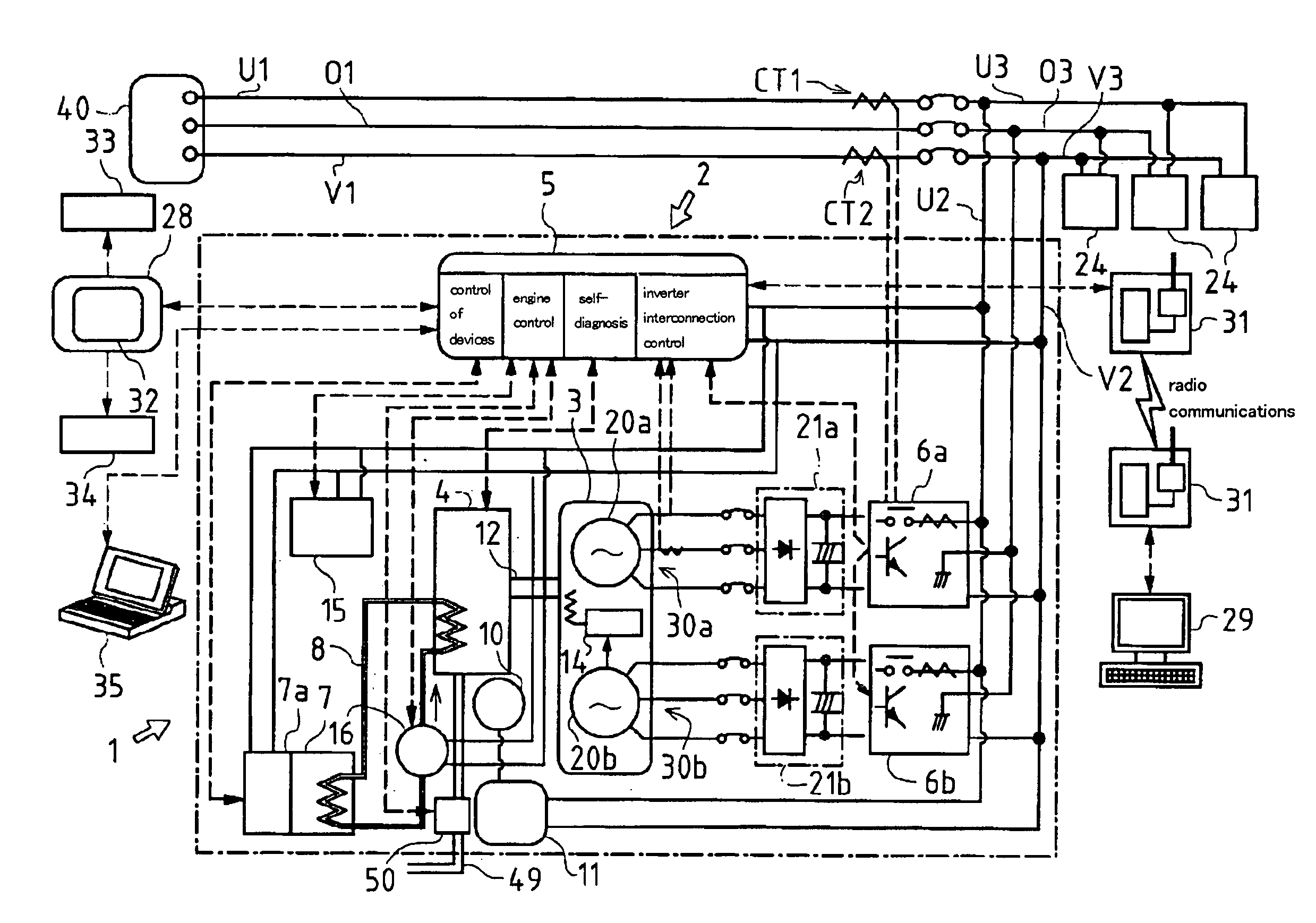
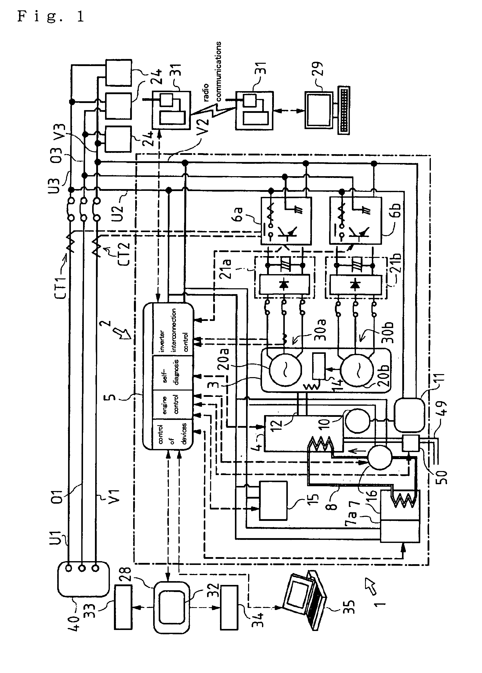
[0150]A electric power generator set 1′ of the second embodiment mainly comprises an engine 4 and a generator 3, and also comprises a control system 2 for controlling these devices. The control system 2 has a control unit 5 for controlling these devices and an operation-and-display unit 28 as means for input / output to the control unit 5. The electric power generator set 1′ has a water-heat energy recovery mechanism.

[0151]The electric power generator set 1′ of the second embodiment has the same engine 4 and generator 3 and the same interconnection with a commercial electric power supply 40 serving as an external electric power supply via inverters 6a and 6b as those of the electric power generator set 1 of the first embodiment.

[0152]Explanation will be given on the water-heat energy recovery mechanism of the electric power generator set 1′...

third embodiment

[0233]Next, explanation will be given on an electric power system constructed by connecting a plurality of electric power generator sets in parallel as the present invention.

[0234]Firstly, explanation will be given on an entire construction of this electric power system 101 according to FIG. 15. The electric power system 101 comprises a plurality of electric power generator sets 102 and a control system 110. Each pair of neighboring electric power generator sets 102, i.e., each pair of neighboring later-discussed control units 105 are mutually connected through communication lines 103 for communication of control signals and various data. In this embodiment, the communication lines 103 adopt the multidrop type connection facilitating for easy extension of the electric power generator sets 102.

[0235]In the electric power system 101, each of the electric power generator sets 102 connects its output side to electric power transmission lines 109 so as to interconnect to a commercial ele...


PUM


Abstract

A control unit (5) for controlling each device which constitutes a electric power generator set (1) is provided with an operation-and-display device (28) so constituted as to calculate each electric power value data and each electric energy data on external electric power, generated electric power, and load electric power on the basis of sensed data on each value of external electric power and generated electric power transmitted from inverters (6a, 6b) and as to store these calculated data and the sensed data, and connected to the electric power generator set (1) by wires or radio. A cogeneration system comprising the electric power generator set (1) is so constituted that data on the electric power generation current value of the external electric power source and the electric power generator set (1) and data on water-heat energy are sensed and transmitted to the control system (2), and that the control system calculates data on an external electric energy, a generated electric energy, a load electric energy, a water-heat energy recovery quantity, and an energy efficiency to display the calculated data on the operation-and-display device (28).

Description

[0001]This application is the U.S. National Phase under 35 U.S.C. §371 of International Application PCT / JP03 / 01140, filed on Feb. 4, 2003, which claims priority of Japanese Patent Application Nos. 2002-36680, 2002-36681 and 2002-36730, all filed on Feb. 14, 2002. The International Application was published under PCT Article 21(2) in a language other than English.TECHNICAL FIELD OF THE INVENTION[0002]The present invention relates to an electric power generator set having a generator driven by an engine and having an ability of interconnecting with an external electric power supply. Furthermore, the present invention relates to an electric power supply system comprising the electric power generator set.BACKGROUND ART[0003]Recently, an electric power generator set comes to be used for supplying electric power consumption apparatuses (loads) with electric power, wherein the electric power generator set can connect a circuit of electric power (internal electric power) generated by a gene...

Claims


Application Information

Patent Timeline
Patent Type & Authority Patents(United States)
IPC IPC(8): F02G5/00F02G5/04H02J3/24H02J3/46H02J3/38H02J3/00H02P9/04H02J13/00
CPCF02G5/04H02J3/005H02J3/38H02J3/46H02P9/04H02J13/001H02J2003/007Y02E20/14Y04S10/12Y04S10/40Y02T10/166Y04S10/30Y04S40/22Y02E60/74Y02E60/76Y02E40/72H02J13/00001H02J2203/20H02J13/00002H02J13/00034Y02E60/00Y02T10/12Y04S40/20H02J3/466H02J3/007G01R21/00Y02E40/70
Inventor HIBI, SHINJITOKIWA, MASAYOSHIFUJISAWA, TOSHINOBUKANEMOTO, TADATATSUYOSHIMOTO, HIROSHIYAMAMURO, KOZOFUKAE, MAMORU
Owner YANMAR CO LTD
Why Eureka
Try Eureka