
Phase-locked battery charge system

a technology of phase-locked batteries and charging systems, applied in the direction of secondary cell servicing/maintenance, electrochemical generators, transportation and packaging, etc., can solve the problems of battery not being 100% fully charged so easily, battery charge takes too long, and usually exceeds 10 hours, so as to reduce the charging time, ensure a safe condition for charging batteries, and attractive charging performance

Inactive Publication Date: 2005-08-09
CHEN LIANG JUI
View PDF2 Cites 35 Cited by
  • Summary
  • Abstract
  • Description
  • Claims
  • Application Information

AI Technical Summary

Benefits of technology

"The invention is a battery charge system that uses a phase comparator, current pump, battery, differential amplifier, and voltage control oscillator to automatically track and lock onto a specific phase. This system provides faster and safer charging with better current control, and is low-cost and easy to use. It solves the problems of slow trickle charging, unstable bulk current charging, and ineffective constant-voltage / constant-current charging, while also providing better performance than fuzzy quick charging systems."

Problems solved by technology

1. The trickle charge strategy has the advantages of simple circuit structure and low cost, but the battery charge takes too long, which usually exceeds 10 hours.
Therefore, it is generally used for overnight charge only.2. The bulk current charge strategy adopts a current larger than that of the trickle charge, but it has a disadvantage that the battery cannot be 100% fully charged so easily according to the voltage detected precision, and thus undercharge or overcharge often occurs.3. The constant-voltage / constant-current charge strategy originally can prevent overcharge effectively, and thus lengthening the charging time.
Furthermore, open control architecture is adopted for the traditional constant-voltage / constant-current charge strategy, which is theoretically not safe enough for the control.4. The fuzzy quick charge system having the active state-of-charge detection capability definitely can reduce the charging time, and assure a safe condition for charging batteries.
Although it has a very attractive charging performance, its shortcoming resides on that the circuit architecture is too complicated and requires high production costs.

Method used


Image

  • Phase-locked battery charge system
  • Phase-locked battery charge system
  • Phase-locked battery charge system

Examples


Embodiment Construction

[0030]To make it easier for our examiner to understand the objective of the invention, its structure, innovative features, and performance, we use a preferred embodiment together with the attached drawings for the detailed description of the invention.

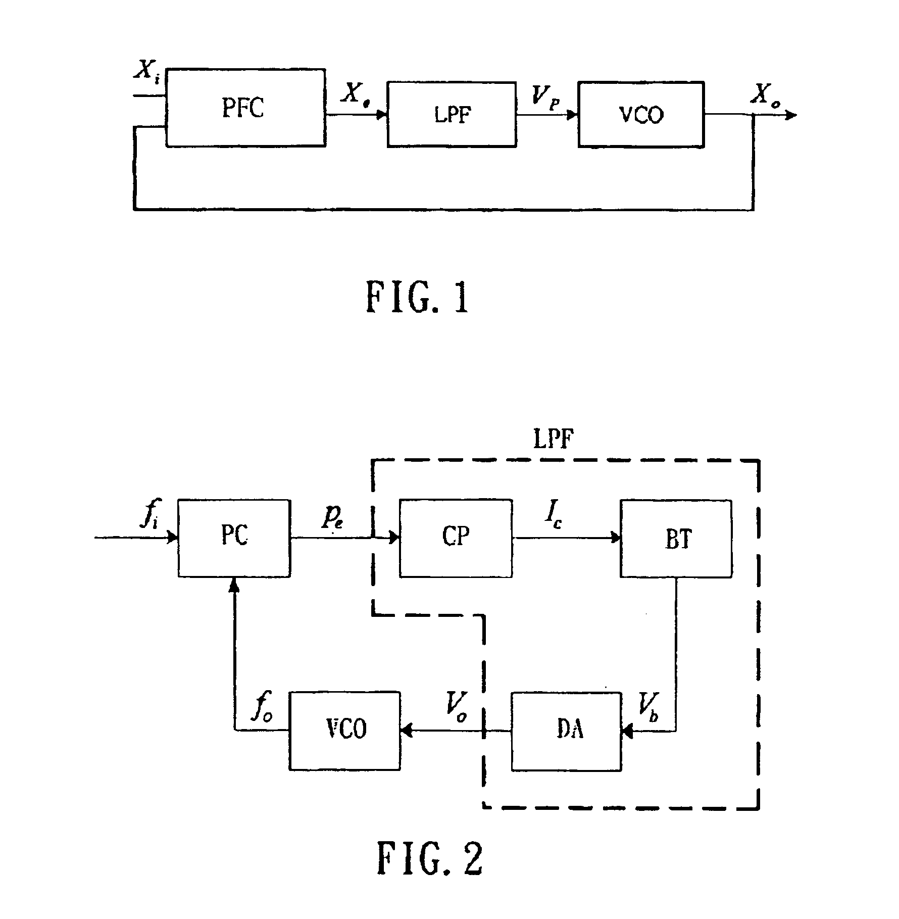
[0031]Please refer to FIG. 1 for the basic architecture of the phase / frequency-locked loop circuit, wherein Xi, Xo, Xe, and Xp are respectively input phase / frequency Xi, output phase / frequency Xo, phase / frequency error Xe, and pump voltage Xp.

[0032]The Phase / Frequency Comparator (PFC) is used to compare the input phase / frequency Xi and the output phase / frequency Xo to obtain the phase / frequency error Xe. The low pass filter (LPF) acts as a phase / frequency driver for the voltage control oscillator VCO. The phase / frequency-locked loop circuit itself is a servo system, which can be used as a way of minimizing the phase / frequency error to zero, such that the phase / frequency of the voltage control oscillator (VCO) approaches the reference p...


PUM

PropertyMeasurementUnit
voltageaaaaaaaaaa
frequencyaaaaaaaaaa
charge currentaaaaaaaaaa

Abstract

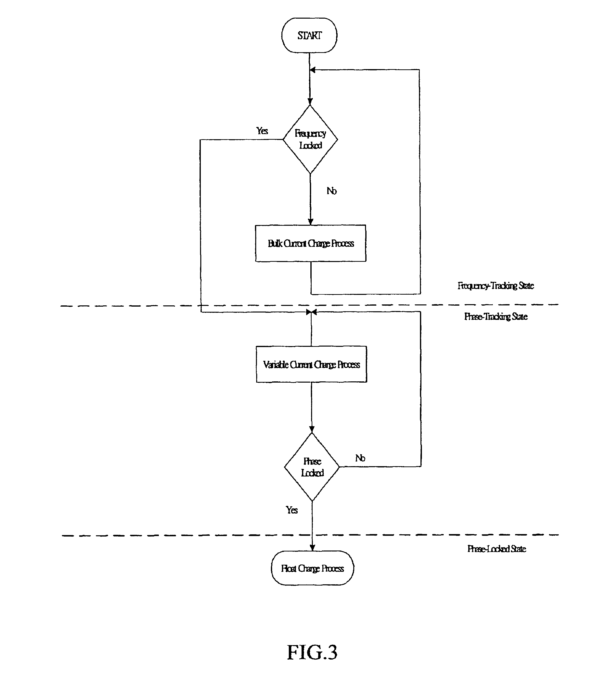
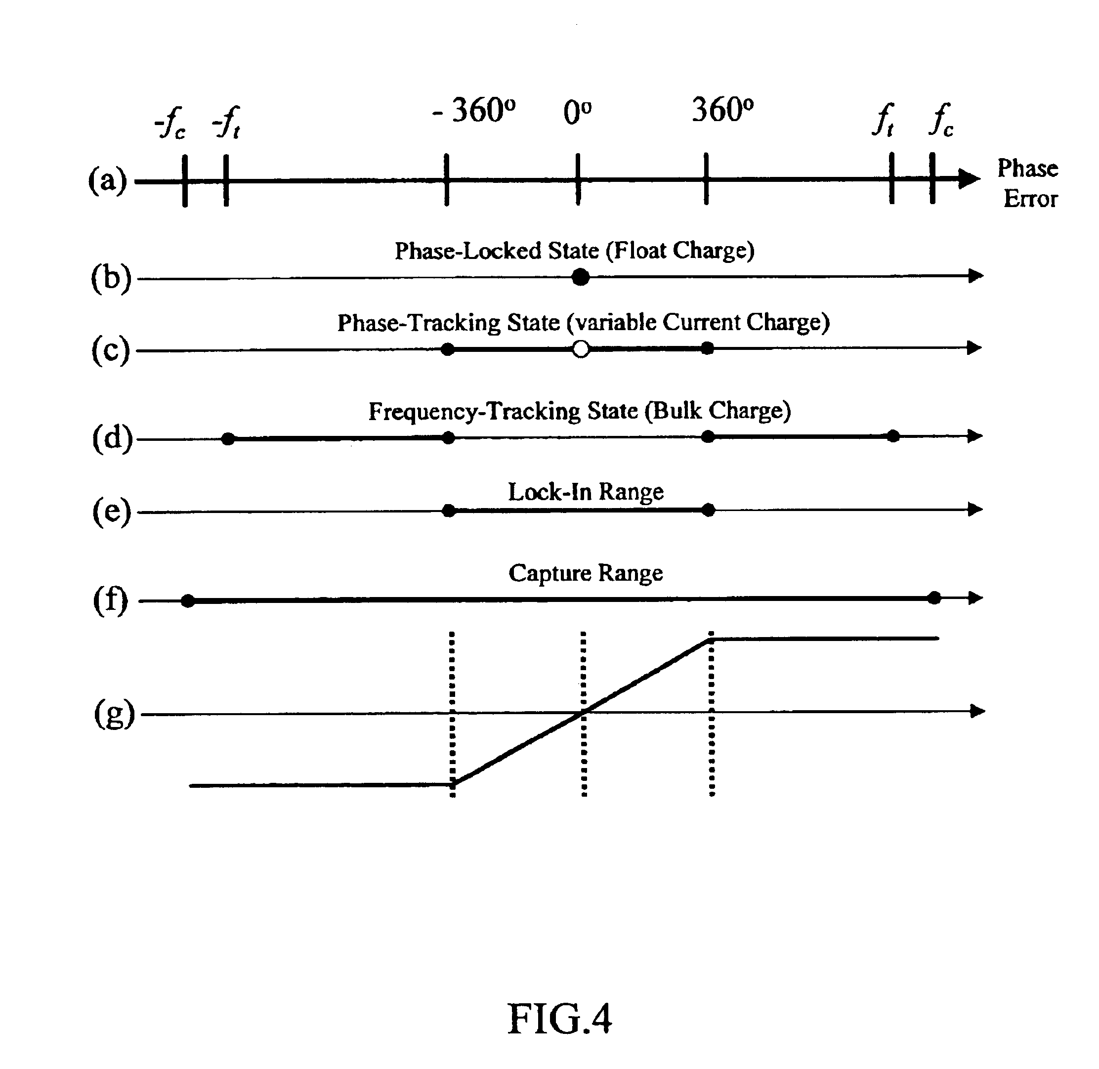
In a phase-locked battery charge system, the structure its circuit is similar to a phase-locked loop; by means of its specific auto-tracking and auto-locking capabilities, a complete battery charge process can be accomplished automatically in the order of bulk current charge, variable current charge, and float charge. Therefore, this invention features with its simple circuit structure, good charge current, and assured safe charge effect.

Description

BACKGROUND OF THE INVENTION[0001]1. Field of the Invention[0002]This invention relates to a phase-locked battery charge system, more particularly to a battery charging system emphasizing on simple circuit structure, good charge current, and safe charge conditions.[0003]2. Description of the Related Art[0004]In general, there are different kinds of secondary batteries including lead acid batteries, Nickel-Cadmium batteries, Nickel-Hydrogen batteries, and Lithium-Ion batteries, and thus many charging strategies for the foregoing batteries have been developed, such as a constant trickle current charge, bulk current charge, and constant-voltage / constant-current charge (or also known as constant-voltage restricted-current charge or two-stage charge).[0005]Further, the most popular constant-voltage / constant-current battery charge strategy uses the bulk current to charge a battery from the beginning until a predetermined final voltage is reached. After the predetermined voltage is reached,...

Claims


Application Information

Patent Timeline
Patent Type & Authority Patents(United States)
IPC IPC(8): H01M10/46H01M10/42H02J7/00H01M10/44
CPCH02J7/0052H02J7/0073H02J7/0071H02J7/00
Inventor CHEN, LIANG-JUI
Owner CHEN LIANG JUI
Learn More