Supercharge Your Innovation With Domain-Expert AI Agents!

Infrared integrating sphere

a technology of integrating spheres and infrared light, applied in the field of infrared integrating spheres, can solve the problems of inefficiency, inconvenient operation, and inability to generally agree upon reflectance standards,

Inactive Publication Date: 2005-08-09
THE UNITED STATES OF AMERICA AS REPRESENTED BY THE SECRETARY OF THE NAVY
View PDF4 Cites 17 Cited by
  • Summary
  • Abstract
  • Description
  • Claims
  • Application Information

AI Technical Summary

Benefits of technology

[0002]Accordingly, an object of this invention is to provide a novel integrating sphere testing system that can measure the diffuse reflectance of samples in the infrared.
[0004]Another object of the invention is to enable one to reposition samples within the system by means external to it, so that one can make a plurality of measurements to test the angular dependence of a sample's diffuse reflectance without needing to vent and replenish the system's atmosphere between any of the plurality of measurements.
[0005]Another object of the invention is to enable one to selectively vary sample temperature, so at to allow testing of the temperature dependence of the sample's infrared diffuse reflectance. In accordance with these and other objects made apparent hereinafter, the invention provides an integrating sphere disposed in an airtight chamber under an atmosphere that does not absorb infrared frequencies. The sphere has two positions where a sample may be mounted, one at the sphere's center, another on the sphere's wall, each position corresponding to a different mode by which the sphere can measure diffuse reflectance. In one mode, a rod disposed along a radius vector of the sphere acts as a mounting pedestal for a center-mount sample, disposing the sample at the sphere's geometrical center. The rod is rotatively mounted about its elongate axis so that a center-mounted sample can about with the rod is elongate axis. The rod penetrates the sphere and the airtight chamber, terminating in a handle by which the rod can be rotated as above described, enabling one to select the incidence angle of the beam on the center mounted sample. In this mode one can reposition the pedestal to systematically examine the angular dependence of a specimen's diffuse reflectance. In addition, a reference or standard can be mounted back-to back with the sample to be measured. By having the positioning handle of the rod external to the test chamber, one can angularly reposition the sample in the sphere externally and without the need to vent and replenish the atmosphere in the apparatus for each angular measurement. In the wall-mount mode, a sample is placed on the sphere's wall, and one uses the sphere's wall as the reference. Adjacent to the wall-mount position is a heater for varying sample temperature, with which one can test the temperature dependence of the diffuse reflectance of the wall mounted sample. The ability to mount samples in either of two modes enables one to compare the diffuse reflectance of the center mounted sample against an identical wall mounted sample for purposes of calibrating data taken in one mode by that taken in the other.

Problems solved by technology

Unfortunately, there are no generally agreed upon reflectance standards beyond 2.5 micrometers in the infrared.
Infrared measurements are complicated by air having several constituents (e.g. water and carbon dioxide), that absorb at infrared frequencies, which can distort or otherwise make less precise such measurements of diffuse reflectance if the measurements are made in an air atmosphere with a single beam spectrophotometer.
Unfortunately, were one to contain any of the present integrating sphere systems in a chamber containing an artificial, non-absorptive atmosphere, one could examine the angular dependence an object's diffuse reflectance only by venting the atmosphere after each test at each angle of incidence, repositioning the object to change the angle of incidence, and recharging the system's artificial atmosphere.
This repeated venting and recharging is most inefficient, inconvenient, and uneconomical.

Method used


Image

  • Infrared integrating sphere
  • Infrared integrating sphere
  • Infrared integrating sphere

Examples


Embodiment Construction

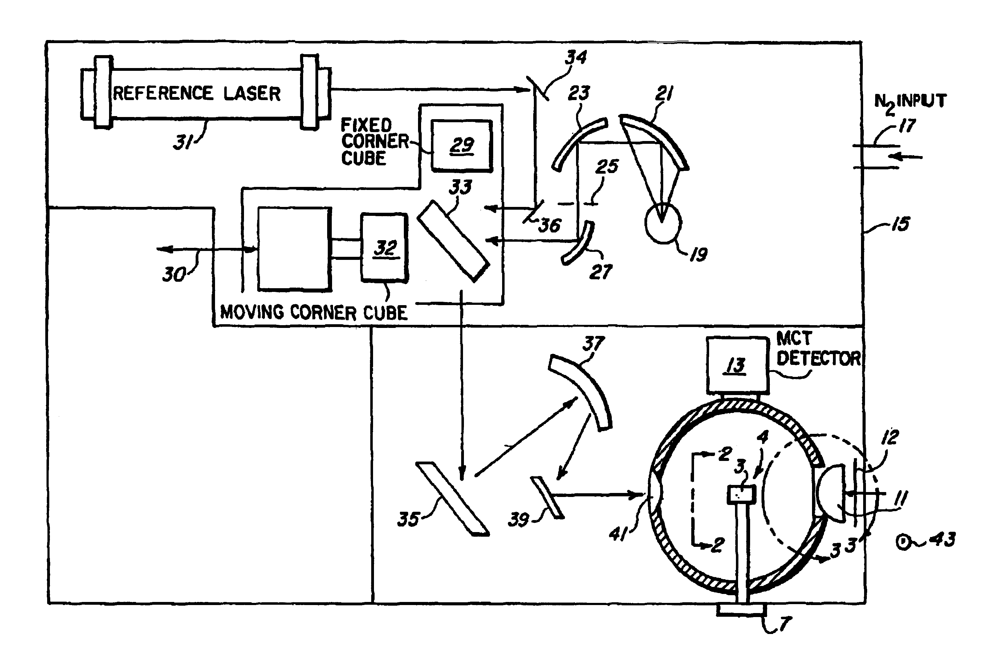
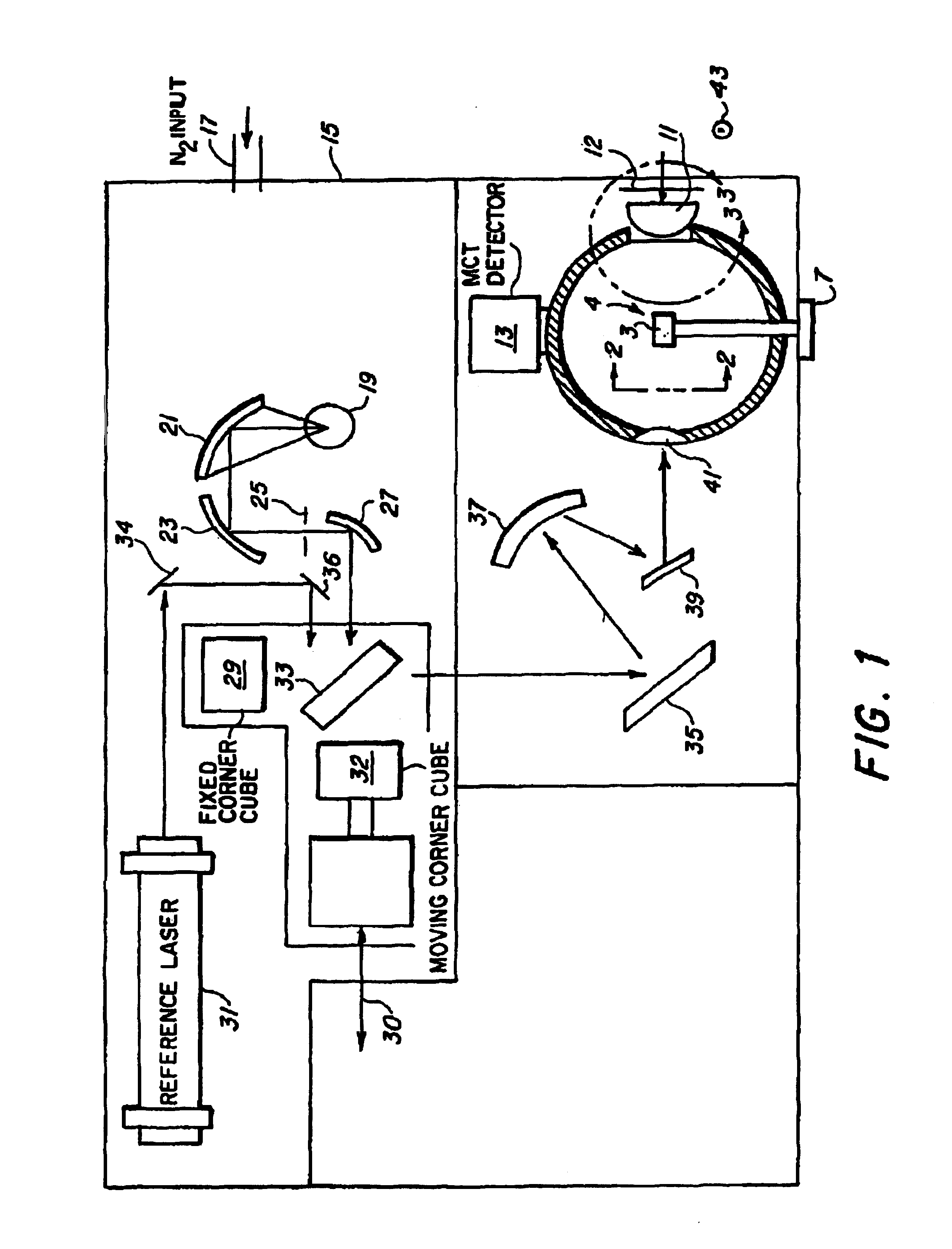
[0010]Referring now to the drawings, wherein like reference numerals designate identical or corresponding parts throughout the several views, and with particular reference to FIG. 1, an integrating sphere 1 is shown disposed within an airtight chamber 15 under a non-absorptive atmosphere fed in at 17. Nitrogen is preferred because it has virtually no absorptance in the infrared, and as such provides a far better atmosphere for chamber 17 than, e.g., air, which contains much water vapor and carbon dioxide, each of which has characteristic infrared frequencies, and whose absorbtance would degrade infrared measurements taken by sphere 1. Chamber 15 has an appropriate door (not shown), so that one can get to the interior of sphere 1 between tests. Sphere 1 is a metal shell of, for example, nickel, whose inner surface is Lambertian (diffusely reflective). Such a surface can be generated by plating a highly reflective (preferably 95% or greater reflectivity) material onto a pre-roughened ...


PUM


Abstract

Disclosed is an integrating sphere for measuring the diffuse reflectivity of material samples in the infrared. The sphere is disposed in an airtight vacuum chamber under an atmosphere that does not absorb in the infrared. The sphere has two positions at which a sample may be mounted, one on a rod at the sphere's center, another on the sphere's wall, each mounting position corresponding to two different modes of testing samples. The rod acts as a mounting pedestal for a center mounted sample, and is rotatably mounted about its elongate vertical axis so that the sample can rotate with the rod in a horizontal plane. The rod penetrates the sphere and the chamber, and terminates in a knob or handle by which the rod can be rotated to position the sample at a preselected angle. Adjacent to the position for wall mounting, there is a sample heater. This configuration allows one to measure diffuse reflectance of a sample as a function of incidence angle and temperature. In the center-mount configuration, the handle enables one to anglularly reposition a center mounted sample without the need to vent and replenish the chamber's atmosphere after each test.

Description

BACKGROUND OF THE INVENTION[0001]The optical characteristics of a material are important material properties, and can be used, for instance, to assign optical signatures to well-known objects or classes of objects, and to identify such objects or classes of objects remotely. For an opaque object, i.e., one having zero transmittance, the object's directional emittance can be characterized if one knows the object's directional hemispherical reflectance as a function of object temperature and angle of incidence. Many systems for determining reflectance are known, prominent among which are integrating spheres, which for decades have been used to measure the reflectance of diffusely reflecting materials in the UV, visible, and near IR. Unfortunately, there are no generally agreed upon reflectance standards beyond 2.5 micrometers in the infrared. Consequently the reflective properties of materials in the infrared are not well known, and there is a need for integrating sphere systems which...

Claims


Application Information

Patent Timeline
IPC IPC(8): G01N21/01G01N21/47
CPCG01N21/474
Inventor SNAIL, KEITH A.CARR, KEVIN F.
Owner THE UNITED STATES OF AMERICA AS REPRESENTED BY THE SECRETARY OF THE NAVY
Features
  • R&D
  • Intellectual Property
  • Life Sciences
  • Materials
  • Tech Scout
  • Unparalleled Data Quality
  • Higher Quality Content
  • 60% Fewer Hallucinations
Learn More