Non-invasive plaque detection using combined nuclear medicine and x-ray system

Active Publication Date: 2005-08-09
KONINKLIJKE PHILIPS ELECTRONICS NV
View PDF18 Cites 97 Cited by
  • Summary
  • Abstract
  • Description
  • Claims
  • Application Information

AI Technical Summary

Benefits of technology

[0016]The precise targeting of the nuclear camera using the images from the x-ray system to obtain a precise image of the region of interest

Problems solved by technology

In recent years, it has become known that occlusion may occur suddenly, potentially resulting in thrombus formation and angina, myocardial infarction (MI) or sudden death.
These metabolically active vulnerable plaques can remain quiescent and sub-clinical for years then erode or suddenly erupt with an associated deleterious effect on the cardiac system.
One example of a present diagnostic technique that is not as successful as desired is the failure of coronary angiography to predict catastrophic cardiovascular failure.
At present, the clinically available techniques tend to have disadvantages that limit their use in asymptomatic patients or are not as effective as desired in identifying, locating and characterizing vulnerable plaque which are believed to represent the higher risk of fatal CHD.
Even with such diverse diagnostic techniques under development and study for the early identification of vulnerable plaque, the degree of clinical effectiveness is presently less than desired in a clinically practical setting.
However, eventhough conventional nuclear medicine imaging techniques can provide functional images, the total volume of vulnerable plaque is extremely small and the total plaque uptake of tracers u

Method used


Image

  • Non-invasive plaque detection using combined nuclear medicine and x-ray system
  • Non-invasive plaque detection using combined nuclear medicine and x-ray system
  • Non-invasive plaque detection using combined nuclear medicine and x-ray system

Examples


Example

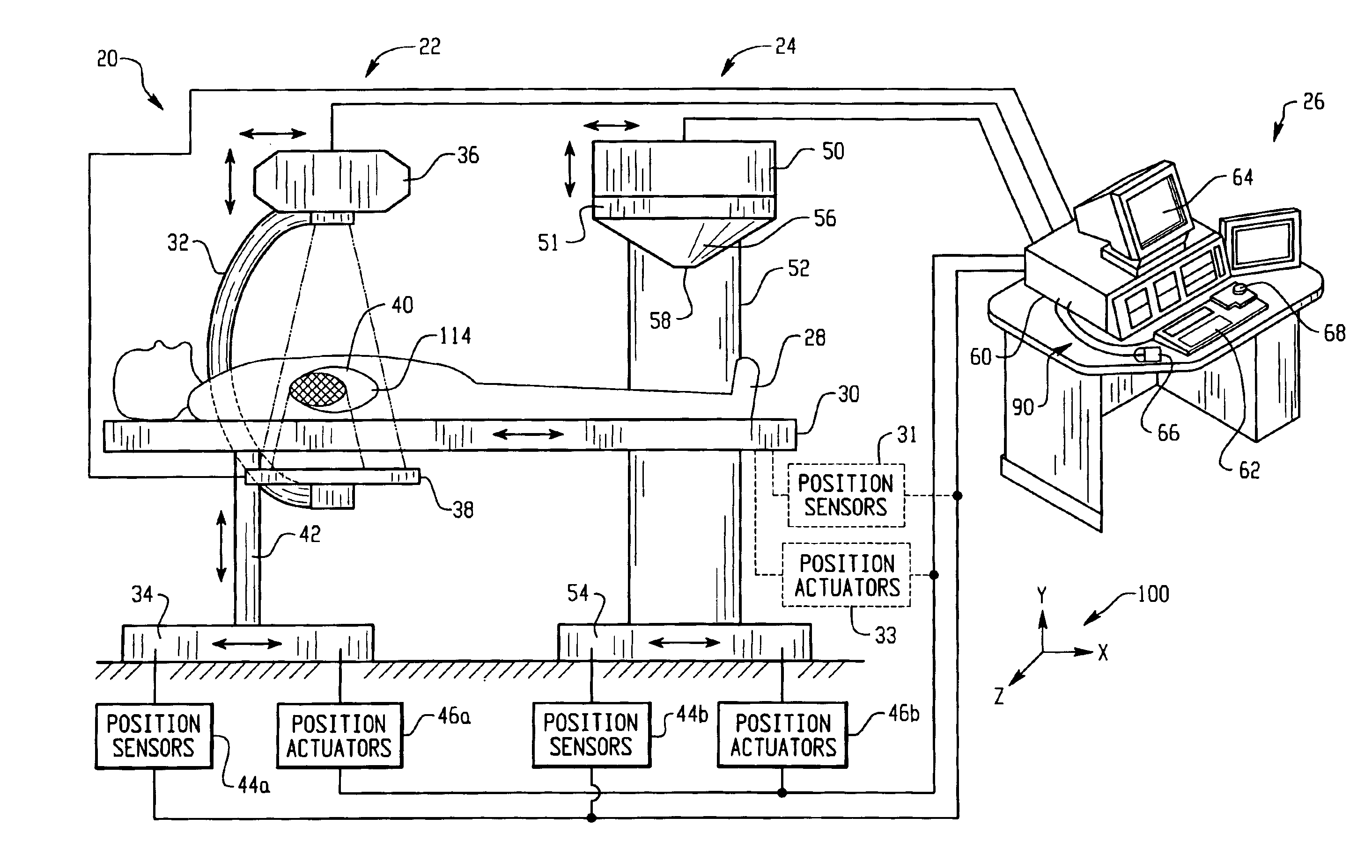
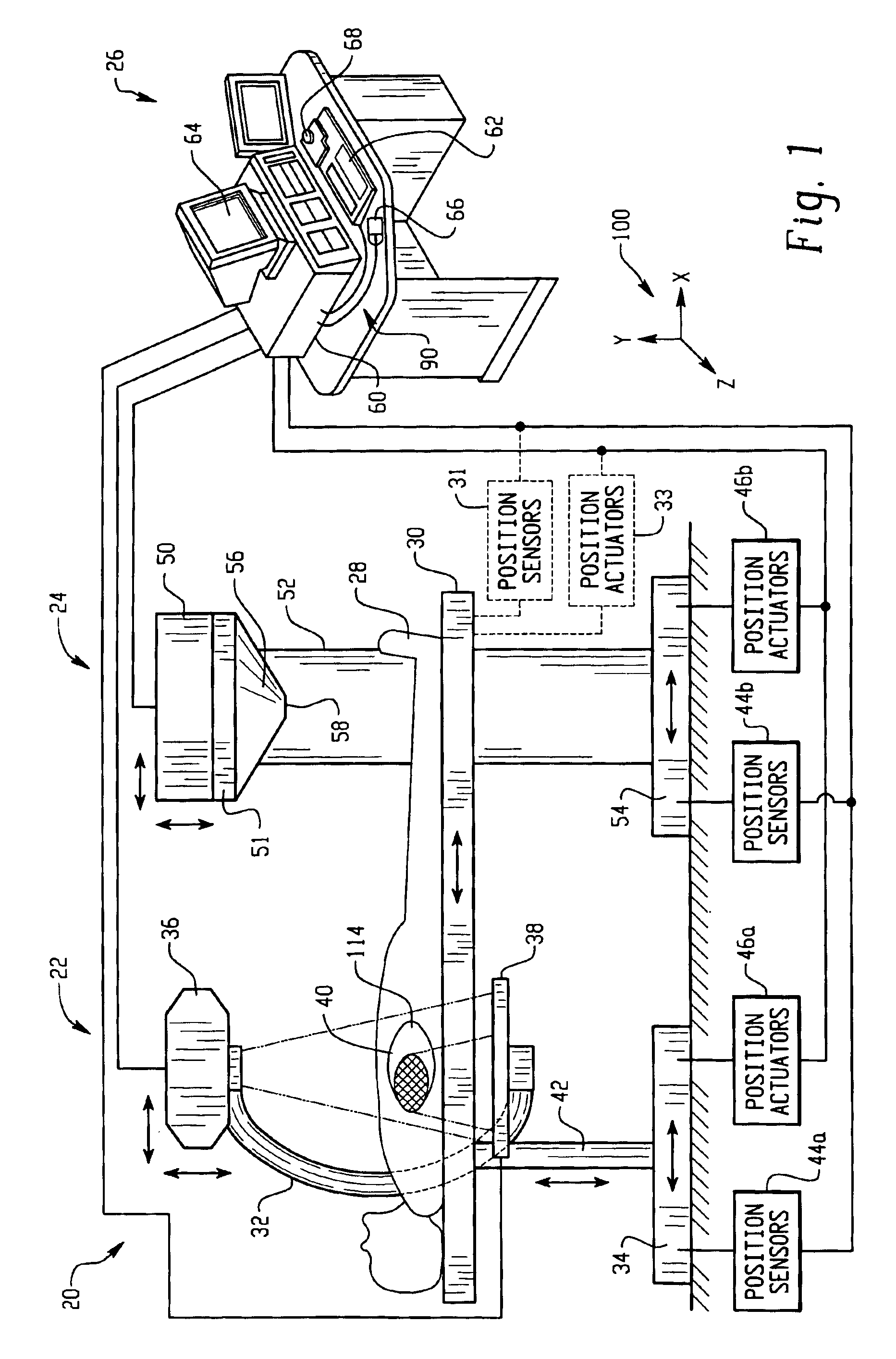
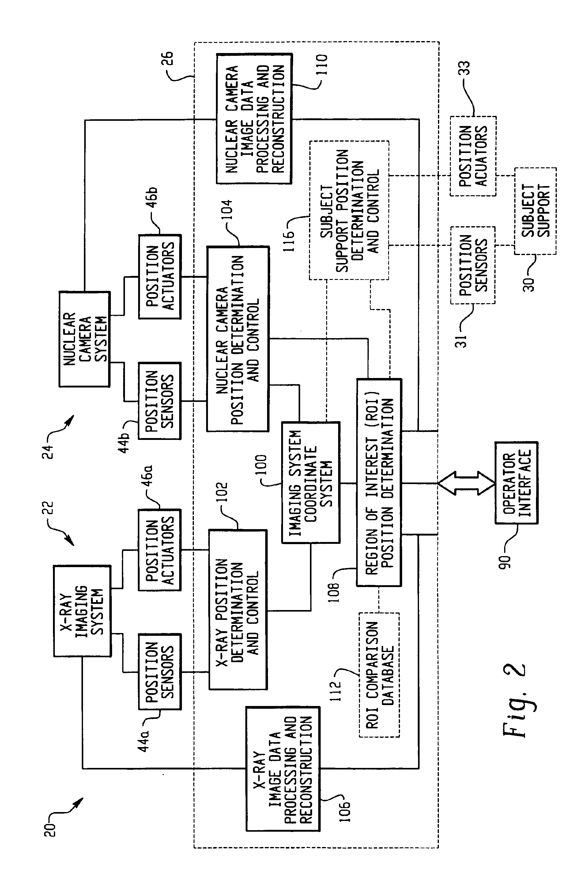
[0024]With reference to FIG. 1, a diagnostic imaging system 20 includes an X-ray sub-system 22, a nuclear camera sub-system 24 and a control console 26. An imaging subject 28 is supported on a subject support 30 in an examination region of the diagnostic imaging system 20.

[0025]The X-ray diagnostic imaging sub-system 22, such as a fluoroscopic and / or radiographic imaging system, includes a support member 32 that is attached to a moveable floor mounted base structure 34. The support member 32 may be coupled to the base structure 34 with a telescopic support column member 42. In the embodiment being described, the support member 32 includes a C-arm.

[0026]An x-ray source or tube 36 is secured to a first free end of the support member 32, and an opposing x-ray detector 38 is secured to a second free end of the support member 32. A fluoroscopic / radiographic examination region is defined between the x-ray source 36 and x-ray detector 38. The x-ray source 36 and x-ray detector 38 can be po...


PUM


Abstract

A diagnostic imaging system (20) comprising a computer workstation (26) for controlling the imaging system, interfacing with an operator and generating images. A coordinate system (100) is in data communication with the computer workstation. The coordinate system (100) is adapted to describe relative position of components in the diagnostic imaging system (20). A subject support (30) is describable within the coordinate system and an X-ray sub-system (22) is positionable around the subject support (30). Position sensors (44a) are operatively connected to the x-ray sub-system (22) and they provide signals to the workstation (26) indicative of the position of components of the x-ray sub-system (22) within the space represented by the coordinate system. A nuclear camera sub-system (24) is positionable around the subject support (30). Position sensors (44b) are operatively connected to the nuclear camera sub-system (24) and provide signals to the workstation (26) indicative of position of components of the nuclear camera sub-system within the coordinate system. The workstation (100) includes a region of interest position determination function (108) for determining the position within the imaging system of a region of interest (40) in an image generated by the x-ray sub-system (22). The region of interest (40) is precisely targeted using the control console (26) for imaging by the nuclear camera (50).

Description

BACKGROUND[0001]The present invention relates to an apparatus and method for detection of plaque and is related to an apparatus and method that is useful to non-invasively locate and identify vulnerable plaque. The present invention finds application in conjunction with a diagnostic imaging system having a nuclear diagnostic imaging sub-system in combination with an x-ray imaging sub-system and will be described with particular respect thereto.[0002]Atherosclerotic cardiovascular disease, especially some aspects of coronary heart disease (CHD), has been thought to develop gradually. In recent years, it has become known that occlusion may occur suddenly, potentially resulting in thrombus formation and angina, myocardial infarction (MI) or sudden death. This shift in study of one operative mechanism for CHD is related to evolving understanding of different types of plaque in coronary arteries that may cause acute coronary syndromes. Present study of plaque in CHD involves identificati...

Claims


Application Information

Patent Timeline
IPC IPC(8): A61B6/08A61B6/00A61B6/04
CPCA61B6/037A61B6/08A61B6/4441A61B6/469A61B6/504A61B6/5235A61B6/04
Inventor SHAO, LINGXIONGBAI, CHUANYONGDURBIN, MARY K.
Owner KONINKLIJKE PHILIPS ELECTRONICS NV
Why Eureka
Try Eureka