Measuring network jitter on application packet flows

Inactive Publication Date: 2005-08-09
MICROSOFT TECH LICENSING LLC
View PDF5 Cites 124 Cited by
  • Summary
  • Abstract
  • Description
  • Claims
  • Application Information

AI Technical Summary

Benefits of technology

[0011]Records of sent packets are associated with records of received packets so that the time a packet was sent can be compared to the time the same packet was received. In the case of IP networks, the unique packet identifier rolls over back to zero after every 64k packets sent by the computer so som

Problems solved by technology

As a result of the methods of handling congestion, applications face variations in the time needed to transport data (network latency) and in the amount of data lost in transmission.
Real-time video and audio applications, for example, cannot tolerate large variations in either latency or in data loss.
While the benefits of QoS guarantees are generally acknowledged, those benefits are difficult to measure accurately.
Another problem with measuring latency stems from differences in the clocks on the sending and receiving computers.
Complex latency measurement tools exist, often relying on radios, satellite receivers, or modems to synchronize the clocks of the s

Method used


Image

  • Measuring network jitter on application packet flows
  • Measuring network jitter on application packet flows
  • Measuring network jitter on application packet flows

Examples


Example

[0033]The following description is based on possible embodiments of the invention and should not be taken as limiting the invention in any way. The first section presents an exemplary hardware and operating environment in which the present invention may be practiced. The next two sections describe network jitter and present one way to measure jitter. These two sections are based on U.S. patent application Ser. No. 09 / 537,995, “Method and System for Accurately Calculating Latency Variation on an End-to-End Path in a Network.” The final section builds on the previous sections, describing aspects of the present invention as another method for measuring network jitter.

Overview of a General-Purpose Computer

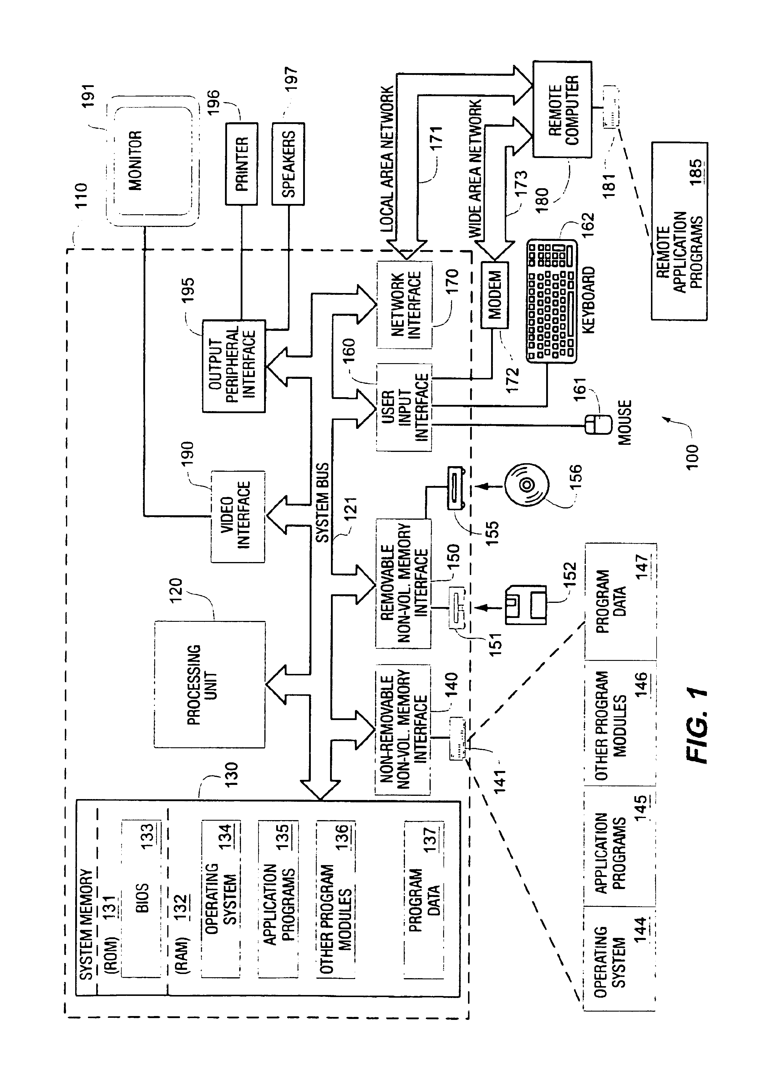
[0034]FIG. 1 illustrates an example of a suitable computing system environment 100 on which the invention may be implemented. The computing system environment 100 is only one example of a suitable computing environment and is not intended to suggest any limitation as to the scope of us...


PUM


Abstract

A method is described for measuring the jitter experienced by an application's network traffic. The measurement is based solely on packets sent or received by the application itself. The method does not alter the application's packets, in particular, it does not add a timestamp to the packets before they are sent. Instead, it creates a table that stores unique identifiers of the application's packets along with the time the packets are sent. On the receiving computer, a similar table is created that stores the unique packet identifiers along with the time the packets are received. Records of sent packets are associated with records of received packets so that the time a packet was sent can be compared to the time the same packet was received. The resulting data are processed to calculate network jitter and packet loss ratios.

Description

TECHNICAL FIELD[0001]The present invention relates generally to computer networks, and, more particularly, to measuring variations in the latency of transmissions over computer networks.BACKGROUND OF THE INVENTION[0002]Traffic flowing from an application running on one computer to an application running on another computer might pass through several network elements such as operating system queues, network adapter cards, LANs, routers, and the like. Each element transmits data at a finite rate so each element has the potential to slow the passage of the traffic. Congestion occurs whenever the rate at which data are sent to a network element exceeds the rate at which the network element transmits the data. Network elements may cope with congestion by queuing data until the congestion subsides or by discarding data to alleviate the congestion.[0003]As a result of the methods of handling congestion, applications face variations in the time needed to transport data (network latency) and...

Claims


Application Information

Patent Timeline
IPC IPC(8): G06F15/16G06F15/173H04L12/26
CPCH04L12/2697H04L43/087H04L43/50H04L43/106
Inventor SUNDARAM, RAJESHKANIYAR, SANJAY N.
Owner MICROSOFT TECH LICENSING LLC
Why Eureka
Try Eureka