Height measuring apparatus
- Summary
- Abstract
- Description
- Claims
- Application Information
AI Technical Summary
Benefits of technology
Problems solved by technology
Method used
Image
Examples
modified embodiment
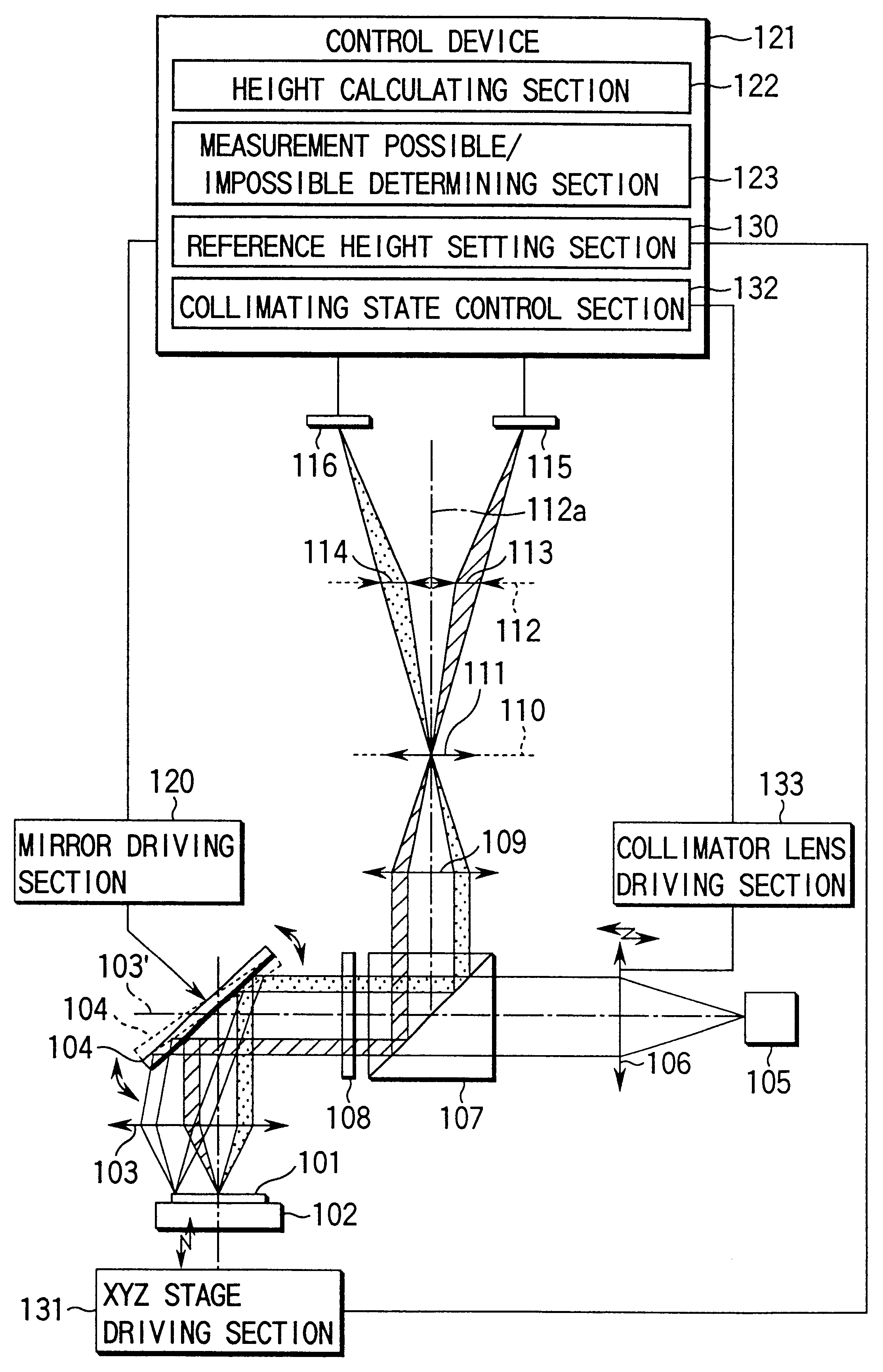
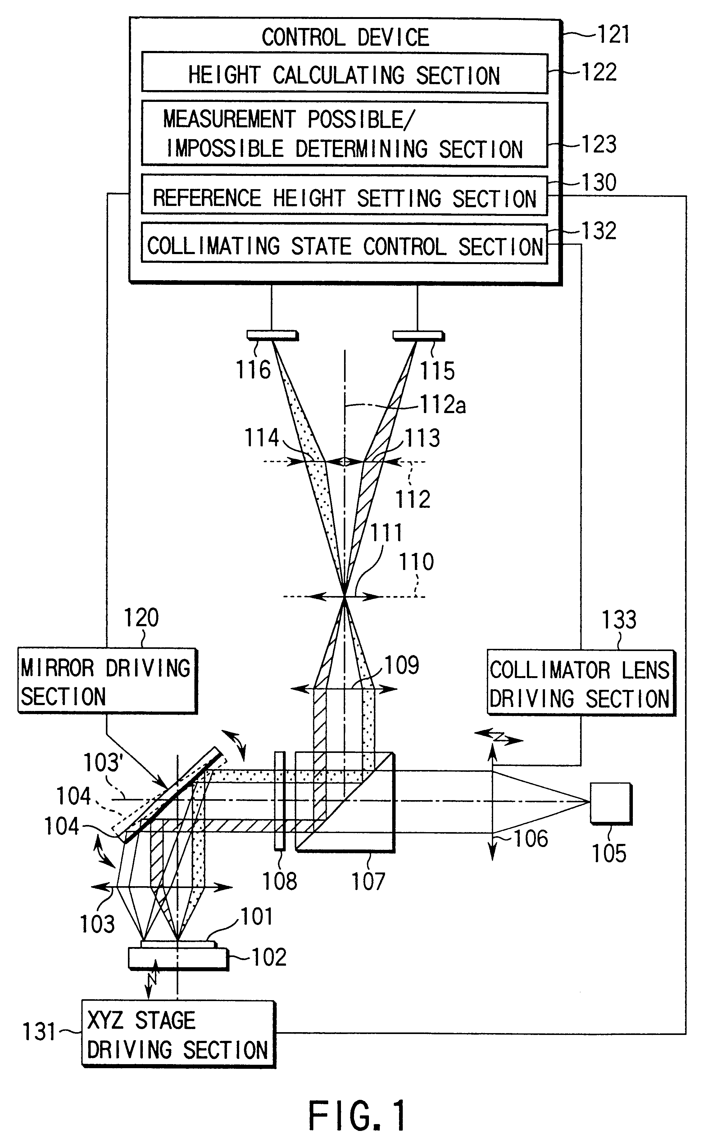
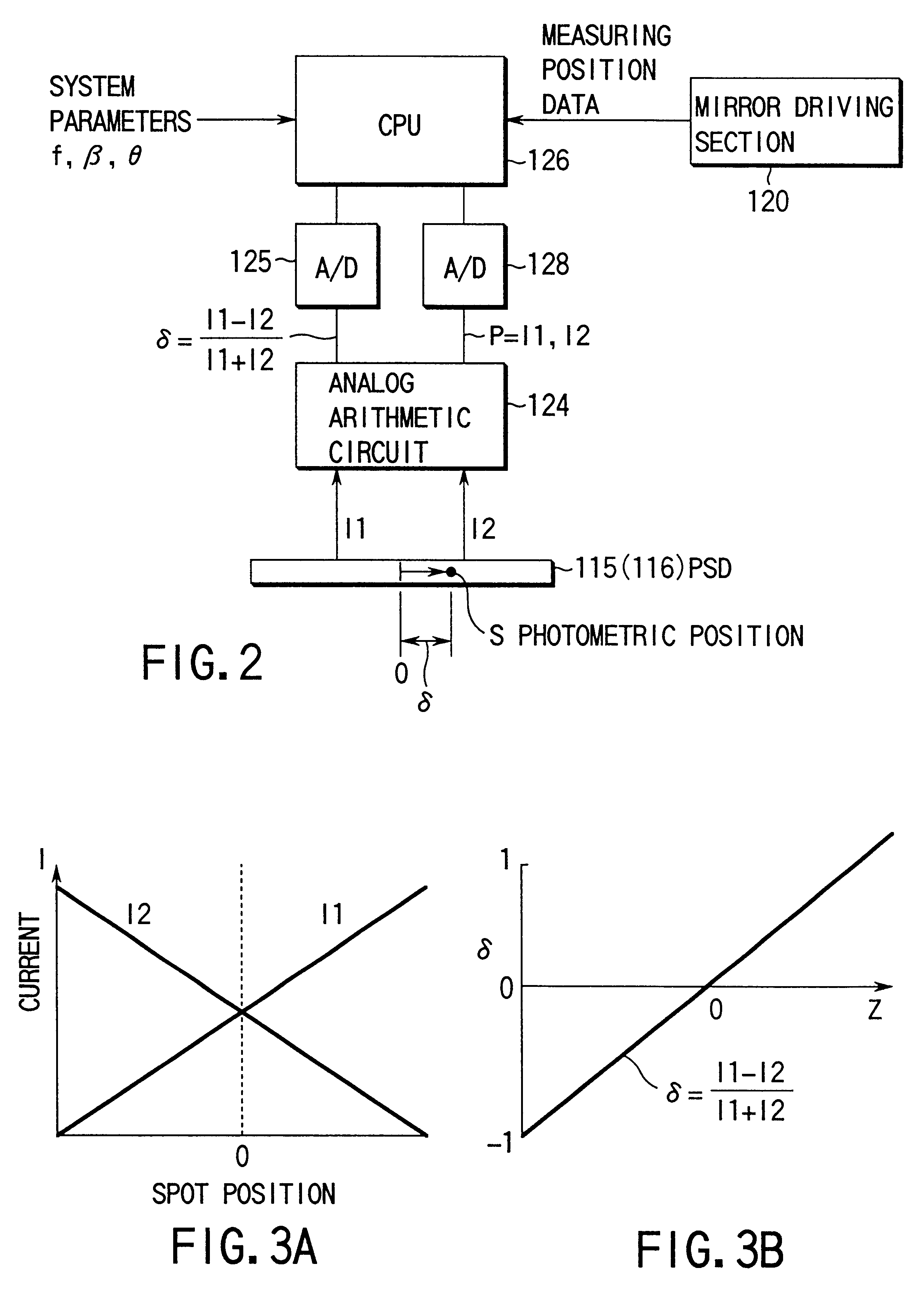
In the first embodiment, the difference between the amount of light the detector 115 receives and the amount of light the detector 116 receives is detected in Step S5-2 from the ratio between the sum signals PR and PL obtained in the detectors 115 and 116, respectively. Instead, the difference may be determined from the absolute value of the difference between the sum signals.
More specifically, the height measured may be considered to be valid (that is, it may be determined that measurement is possible), only if the following holds:
.vertline.(PR-PL) / (PR+PL).vertline.<0.3 (12)
In Step S5-3, too, it is determined whether the distribution of the amount of light is appropriate or not, on the basis of the ratio between the absolute values of the spot position signals .delta.R and .delta.L. Instead, that may be determined from the difference between the absolute values of the spot position signals.
For instance, it may be determined that the height measured is valid (namely, it may be deter...
first embodiment
The first embodiment comprises a pair of detection optical systems, each having a detector (a separator lens and a detector). However, the invention is not limited to this. For example, the apparatus may comprise a pair of such optical systems and another pair of detection optical systems arranged in the direction rotated by 90.degree. around the optical axes of the optical systems of the first pair.
In this structure, the optical systems of the second pair can perform measurement in some cases even if the values measures by the optical systems of the first pair are discarded because the measurement possible / impossible determining section has determined that measurement is impossible. Thus, as much valid measurement results as possible can be obtained. In the case where only one pair of detection optical systems are provided, almost the same effect can be attained, though the function is limited in part.
second embodiment
The second embodiment of the present invention will be described, with reference to FIG. 9.
In the recent IC market, it is demanded that the inspection of ICs be accomplished at high speed. This is because the operation throughput is of vital importance.
In the first embodiment, the first and second detectors 115 and 116 provided for detecting the changes in the position of the light spot are PSDS. Their response speed is lower than the response speed of photodiodes that are designed merely to detect changes in the amount of light. The maximum speed with which the apparatus according to the first embodiment can measure height is determined by the response speed of the detectors 115 and 116 that detect the position .delta. of the light spot moving in accordance with the height of the object 101. Theoretically, it is therefore impossible for the apparatus to inspect Ics at a speed higher than the response speed of the detectors 115 and 116.
In view of the above, the second embodiment is ...
PUM
 Abstract
Description
Claims
Application Information
 - R&D
- Intellectual Property
- Life Sciences
- Materials
- Tech Scout
- Unparalleled Data Quality
- Higher Quality Content
- 60% Fewer Hallucinations
Browse by: Latest US Patents, China's latest patents, Technical Efficacy Thesaurus, Application Domain, Technology Topic, Popular Technical Reports.
© 2025 PatSnap. All rights reserved.Legal|Privacy policy|Modern Slavery Act Transparency Statement|Sitemap|About US| Contact US: help@patsnap.com


