Al technical title is built by PatSnap Al team. It summarizes the technical point description of the patent document.
a safety cone and compact technology, applied in road signs, roads, constructions, etc., can solve the problems of occupying a significant amount of precious space, not having a self-right mechanism, and a challenge in carrying these cumbersome rigid cones, and achieves the effect of convenient storage, carrying or displaying the devi
Inactive Publication Date: 2005-08-16
RAMSTAR MILLS INC
View PDF11 Cites 44 Cited by
Summary
Abstract
Description
Claims
Application Information
AI Technical Summary
This helps you quickly interpret patents by identifying the three key elements:
Problems solved by technology
Method used
Benefits of technology
[0013]In some embodiments, the holding means is a light-emitting device attached to the base via a movable joint such as hinge. The light-emitting device has a housing, a light bulb, batteries, and a switch. The light-emitting device holds down the flexible spring via a locking pin, which is conveniently attached to the movable joint or the base. A hollow or solid body member perturbs from the backside of the light bulb residing end of the housing. The body member, whose shape is not limited to cylindrical, has an overall diameter that is slightly smaller than the diameter of the top loop of the flexible spring such that, when in holding position, the body member fits inside the loops of the flexible spring to prevent them from moving. In certain embodiments, the movable joint has a spring mechanism that causes the light-emitting device to self-erect upon the release of the locking pin. In some embodiments, the flexible safety marker device is integrated with a handle, making it even easier to carry, store, or display the device.
Problems solved by technology
Especially in consumer applications, carrying these cumbersome rigid cones could be a challenge, not to mention that they would take up a significant amount of precious space in a trunk or cargo area of a vehicle.
However, it does not have a self-right mechanism.
Thus, when confronted by an indirect or direct force, e.g., natural wind, passing traffic, or violence, it is likely to fall over or collapse and become a flying or lying object endangering following traffic and / or surrounding people.
However, it does not have a self-right mechanism.
Thus, similar to Kwok's mobile traffic warning sign, when confronted by an indirect or direct force, e.g., natural wind, passing traffic, or violence, Ho's telescopic roadblock is likely to fall over or collapse and become a flying or lying object endangering following traffic and / or surrounding people.
Method used
Image
Click on the blue label to locate the original text in one second.
Reading with bidirectional positioning of images and text.
Examples
Embodiment Construction
[0028]Although the following detailed description contains many specifics for the purposes of illustration, anyone of ordinary skill in the art will readily appreciate that many variations and alterations to the following exemplary details are within the scope of the invention. Accordingly, the following preferred embodiment of the invention is set forth without any loss of generality to, and without imposing limitations upon, the claimed invention.
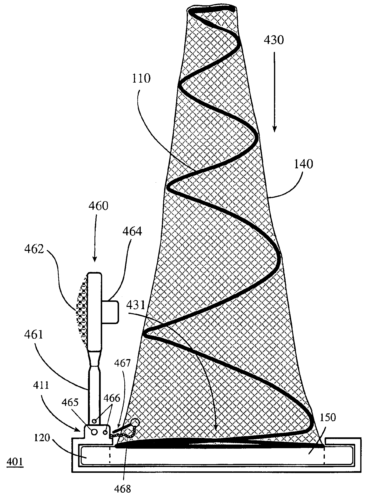
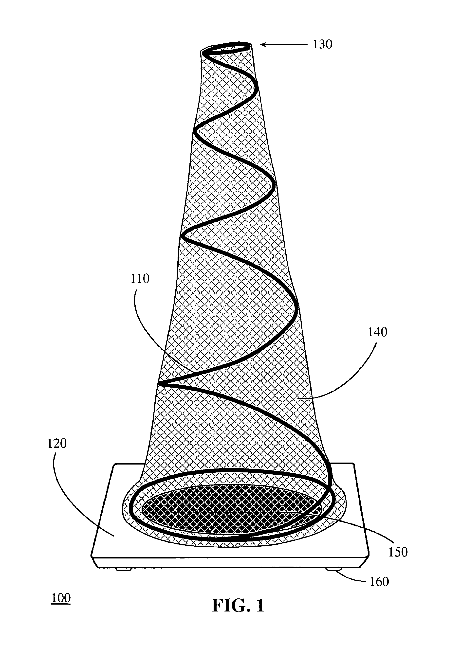
[0029]FIG. 1 shows an exemplary embodiment of a marker device 100 according to the present invention. Marker device 100 includes a base 120 with an opening 150 and a flexible means 110 in the form of a coil or spring. Opening 150 is preferably sufficiently large to allow stacking. The bottom end of the flexible means 110 is attached to the base 120 and preferably coils over and around the center of the base 120 in decreasing diameters without overlapping. In some embodiments, the bottom end of the flexible means 110, which is not limited ...
PUM
Abstract
A compact safety cone that can self-right when in use and be reduced to a compact size when not. The compact safety cone has a base, flexible means, and cover. The spring flexible means coils around the center of the base in decreasing diameters without overlapping. The compact safety cone has a substantially low center of gravity due to the weight distribution among its components. By design, the compact safety cone has a fast impulse response to direct (contact) and indirect (no-contact) perturbations and is capable of being run over or hit by a vehicle and “self-right” substantially immediately after the impact. When not in use, an integrated holding means conveniently and securely keeps the flexible means to the base. The holding means can be, e.g., a cover, lid, light, sign, mirror, box, case, hook, latch, strap, Velcro, pin, lock, etc. In some cases, an optional handle may be included.
Description
CROSS-REFERENCE TO RELATED APPLICATIONS[0001]The present application is a continuation-in-part of a U.S. patent application Ser. No. 10 / 131,316, filed Apr. 23, 2002, now U.S. Pat. No. 6,766,760, which claims priority from provisional patent applications Nos. 60 / 351,557, filed Jan. 23, 2002, and Ser. No. 60 / 360,141, filed Feb. 22, 2002, all of which are incorporated herein by reference. This application also claims priority from a provisional patent application No. 60 / 444,278, filed Jan. 31, 2003, the entire content of which is incorporated herein by reference. This application also relates to a co-pending U.S. patent application Ser. No. 10 / 763,399, filed Jan. 23, 2004, which claims priority from a provisional patent application No. 60 / 442,355, filed Jan. 23, 2003, and a PCT Application No. US03 / 02116, filed Jan. 23, 2003, all of which are incorporated herein by reference.FIELD OF THE INVENTION[0002]The present invention relates generally to traffic marker devices and more particula...
Claims
Application Information
Patent Timeline
Application Date:The date an application was filed.
Publication Date:The date a patent or application was officially published.
First Publication Date:The earliest publication date of a patent with the same application number.
Issue Date:Publication date of the patent grant document.
PCT Entry Date:The Entry date of PCT National Phase.
Estimated Expiry Date:The statutory expiry date of a patent right according to the Patent Law, and it is the longest term of protection that the patent right can achieve without the termination of the patent right due to other reasons(Term extension factor has been taken into account ).
Invalid Date:Actual expiry date is based on effective date or publication date of legal transaction data of invalid patent.