Method and apparatus for single disc ultrasonic cleaning

a technology of ultrasonic cleaning and single disc, applied in the field of methods, can solve the problems of general reduction in the effectiveness of cleaning/removal properties of cleaning baths or solutions, and the likelihood of particle redeposition

Inactive Publication Date: 2005-08-16
SEAGATE TECH HDD HLDG +3
View PDF34 Cites 4 Cited by
  • Summary
  • Abstract
  • Description
  • Claims
  • Application Information

AI Technical Summary

Benefits of technology

[0010]An advantage of the present invention is an improved apparatus for treating surfaces of a single workpiece with ultrasonic energy.
[0011]Another advantage of the present invention is an improved apparatus for treating a single workpiece having a pair of opposed, planar surfaces with ultrasonic energy.
[0012]Yet another advantage of the present invention is an improved method for treating surfaces of a single workpiece with ultrasonic energy.
[0013]Still another advantage of the present invention is an improved method for treating a single workpiece having a pair of opposed, planar surfaces with ultrasonic energy.
[0014]Additional advantages and other features of the present invention will be set forth in the description which follows and in part will become apparent to those having ordinary skill in the art upon examination of the following or may be learned from the practice of the present invention. The advantages of the present invention may be realized and obtained as particularly pointed out in the appended claims.
[0015]According to one aspect of the present invention, the foregoing and other advantages are obtained in part by an apparatus for treating surfaces of a single workpiece with ultrasonic energy, comprising:

Problems solved by technology

(1) the intensity of the ultrasonic (i.e., acoustic) energy field that a surface of a particular workpiece experiences is different for each disc, primarily as a result of the geometric arrangement of the discs and significant variation in the acoustic energy across the bottom of the tank or vessel, for example, arising from the formation of standing (or stationary) acoustic waves rather than progressive (or traveling) waves. For example, FIG. 2 illustrates the large variation in transmitted acoustic energy (measured in terms of power density, watts / unit area) across the bottom surface of a conventional ultrasonic apparatus employing a plurality of bottom-mounted ultrasonic transducers; and
(2) the relatively large tanks or vessels of conventional batch-type ultrasonic treatment apparatus contain a considerable amount of cleaning liquid or bath, which liquid bath is, on average, utilized for a very long interval, typically about 10-12 hours, before being replaced with fresh cleaning solution. However, as the workpieces (e.g., discs) are processed in the tank, particulate matter and other contaminants, such as soluble and / or insoluble materials, are removed from the workpiece surfaces and become suspended and / or dissolved in the cleaning solution, thereby increasing the likelihood of particle redeposition, damage to the workpiece surfaces arising from the mechanical abrading action exerted thereon by the suspended particles, and a general reduction in effectiveness of the cleaning / removal properties of the cleaning bath or solution due to exhaustion of the active ingredients or components thereof, e.g., surfactants, detergents, etc. As a consequence, in order to extend the effectiveness of the cleaning solution, the latter is typically recirculated through a filter, which filter has a further disadvantage of incurring contaminant loading necessitating periodic cleaning and / or replacement of the filter material or cartridge.

Method used


Image

  • Method and apparatus for single disc ultrasonic cleaning
  • Method and apparatus for single disc ultrasonic cleaning
  • Method and apparatus for single disc ultrasonic cleaning

Examples


Embodiment Construction

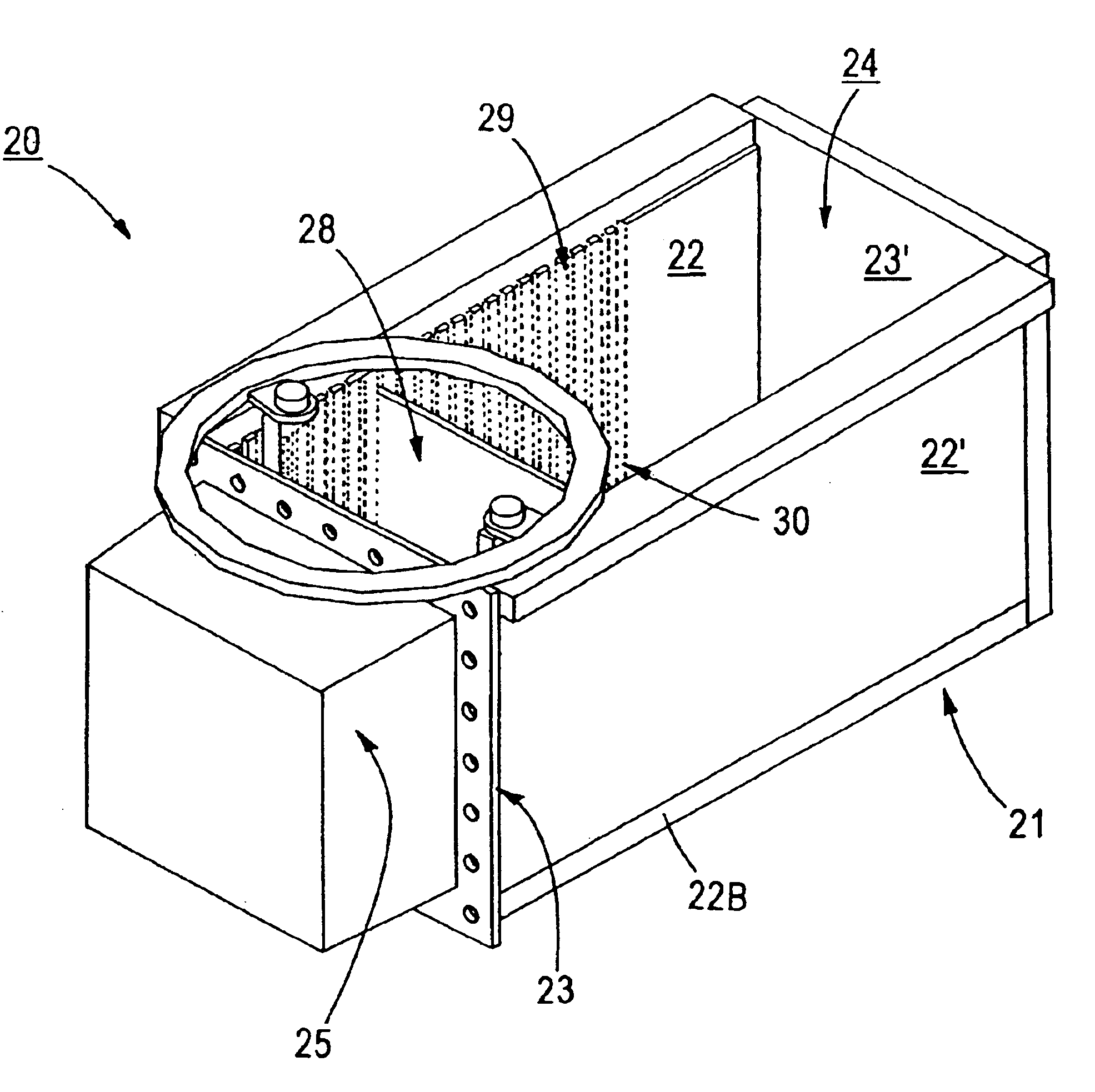
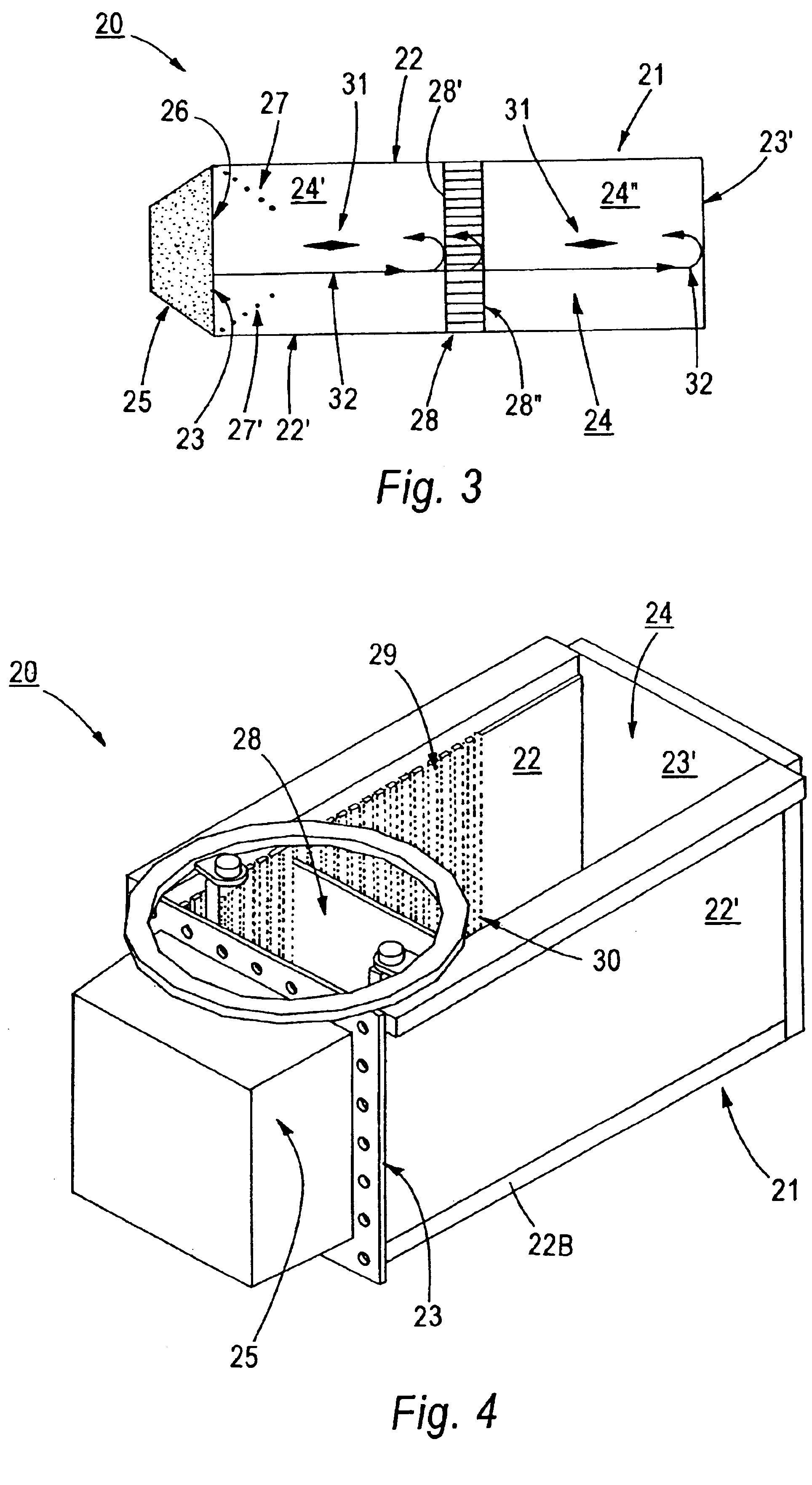
[0050]The present invention is based upon the discovery that a single dual planar-sided workpiece, e.g., a disc-shaped substrate for use in magnetic recording media or a semiconductor wafer utilized in fabrication of IC devices, can be rapidly and cost-effectively subjected to ultrasonic treatment, e.g., for cleaning, desmutting, particulate removal, etc., by means of apparatus and methodology which avoid the aforementioned drawbacks and disadvantages associated with the use of batch ultrasonic treatment techniques utilizing relatively large tanks or vessels. According to the invention, the relatively large tanks with bottom-mounted ultrasonic transducers for simultaneously processing a large plurality of disc-shaped workpieces are replaced with at least one ultrasonic treating apparatus comprised of a relatively small tank with a sidewall-mounted ultrasonic transducer. The at least one tank may be provided with a movable partition for adjustably partitioning the tank or vessel into...


PUM

PropertyMeasurementUnit
diametersaaaaaaaaaa
ultrasonic frequenciesaaaaaaaaaa
distancesaaaaaaaaaa

Abstract

At least one ultrasonic treating apparatus adapted for treating a single workpiece and comprised of a relatively small tank with a sidewall-mounted ultrasonic transducer is provided. The tank may be provided with a movable partition for adjustably partitioning the tank into two sub-chambers, the partition being comprised of a material which is partially reflective and partially transmissive of ultrasonic energy supplied to a liquid within the tank. A reflector is provided within the tank for reflecting the acoustic energy either back to the movable partition or to a material which acts as an absorber of acoustic energy. In the former instance, the acoustic energy can be locally concentrated at a specific spacing from the ultrasonic transducer. In the latter instance, the effectiveness of ultrasonic treatment of the single workpiece is enhanced by favoring formation of progressive waves and minimizing formation of stationary waves.

Description

CROSS-REFERENCE TO PROVISIONAL APPLICATION[0001]This application is a divisional of application Ser. No. 09 / 756,714, filed Jan. 10, 2001, now U.S. Pat. No. 6,619,305.[0002]This application claims priority from U.S. provisional patent application Ser. No. 60 / 175,605 filed Jan. 11, 2000, the entire disclosure of which is incorporated herein by reference.FIELD OF THE INVENTION[0003]The present invention relates to apparatus and methods for treating workpieces with ultrasonic energy. More specifically, the present invention relates to apparatus and methods for performing ultrasonic cleaning of workpieces having a pair of opposed, planar surfaces, for example, disc-shaped workpieces. The invention has particular utility in the manufacture of disc-shaped magnetic and magneto-optic (“MO”) recording media and semiconductor devices employing semiconductor wafer substrates.BACKGROUND OF THE INVENTION[0004]The ever-increasing areal recording densities of magnetic and MO recording media, as in ...

Claims


Application Information

Patent Timeline
Patent Type & Authority Patents(United States)
IPC IPC(8): B08B3/12G11B23/50H01L21/00
CPCB08B3/12G11B23/505H01L21/67057Y10S134/902
Inventor SHARMA, AMBERSHEFFIELD, JOHN EDGAR
Owner SEAGATE TECH HDD HLDG
Why Eureka
Try Eureka