Dual clutch for a transmission with two input shafts

a transmission and input shaft technology, applied in the direction of clutches, non-mechanical actuated clutches, climate sustainability, etc., can solve the problem of complex mechanical drive of the second clutch, and achieve the effect of high torque capacity

Inactive Publication Date: 2005-08-16
FORD GLOBAL TECH LLC
View PDF14 Cites 54 Cited by
  • Summary
  • Abstract
  • Description
  • Claims
  • Application Information

AI Technical Summary

Benefits of technology

[0004]It is therefore the object of the invention to provide a twin clutch of compact construction with a high torque capacity. There should furthermore be the po

Problems solved by technology

However, the drive for the second clutch is very complex mechanically since a complicated li

Method used


Image

  • Dual clutch for a transmission with two input shafts
  • Dual clutch for a transmission with two input shafts
  • Dual clutch for a transmission with two input shafts

Examples


Embodiment Construction

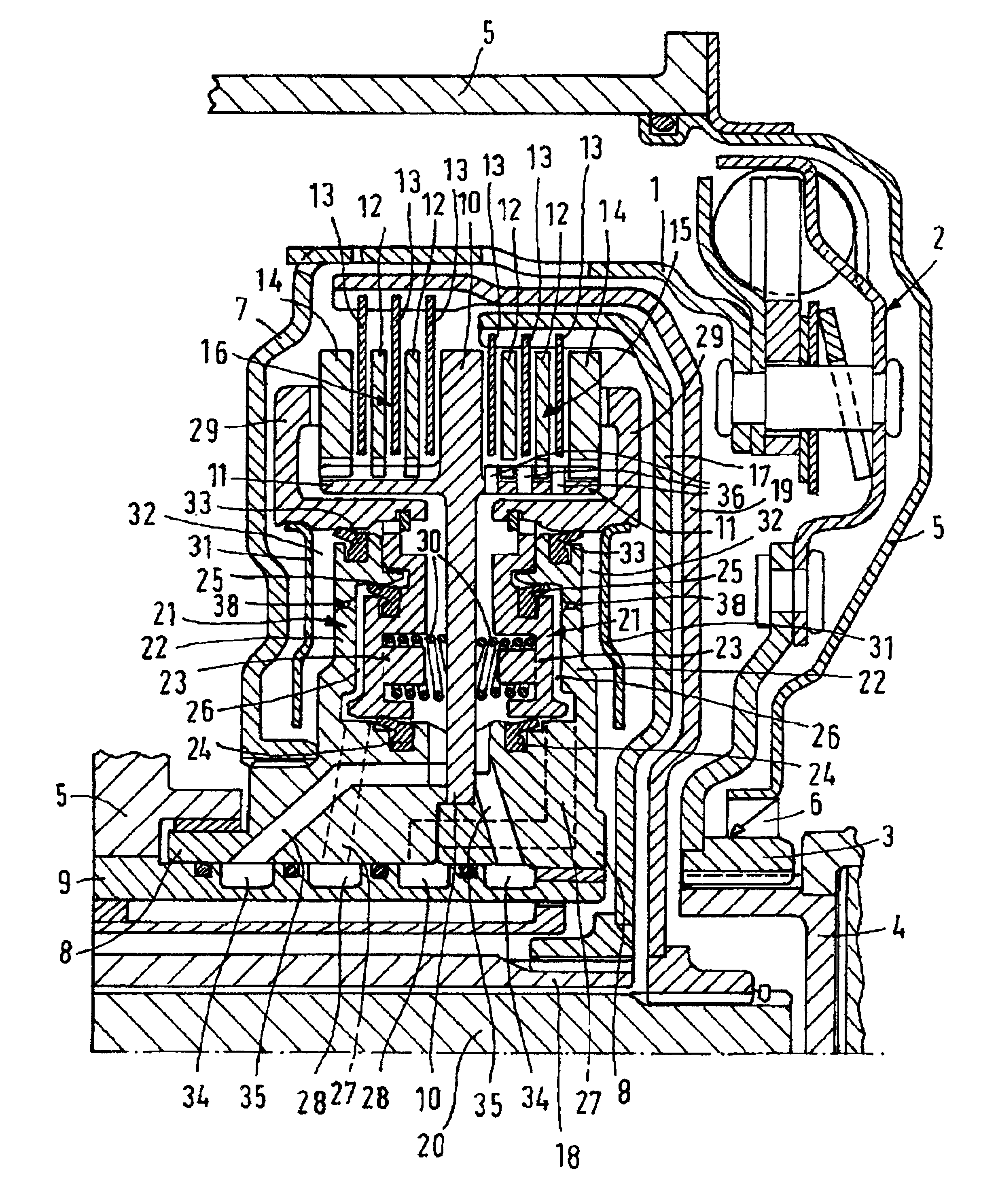
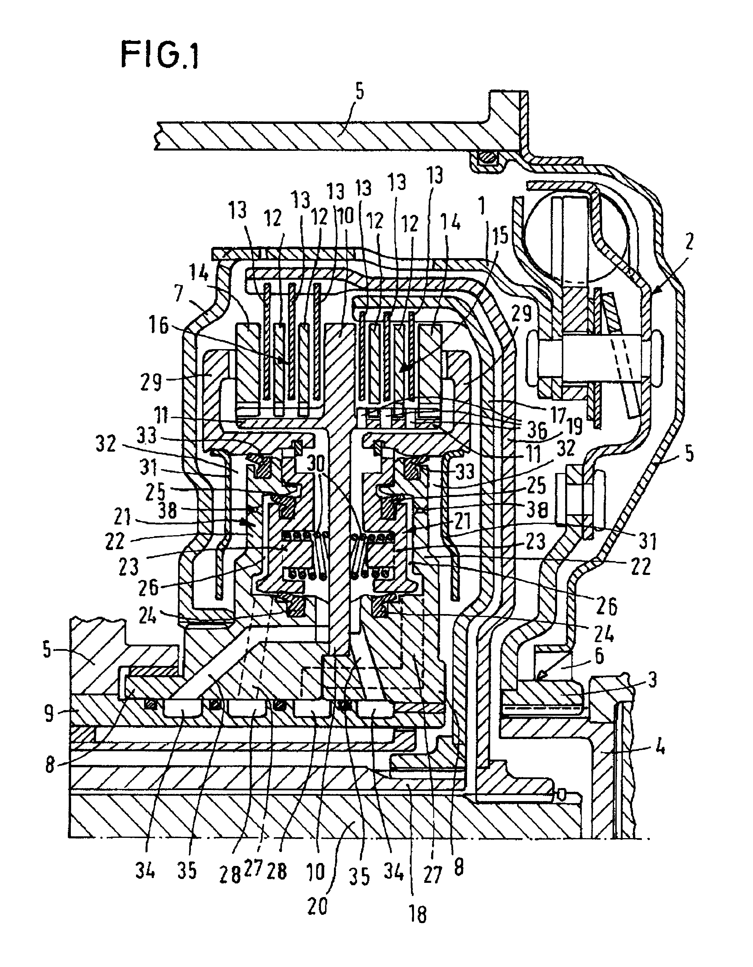
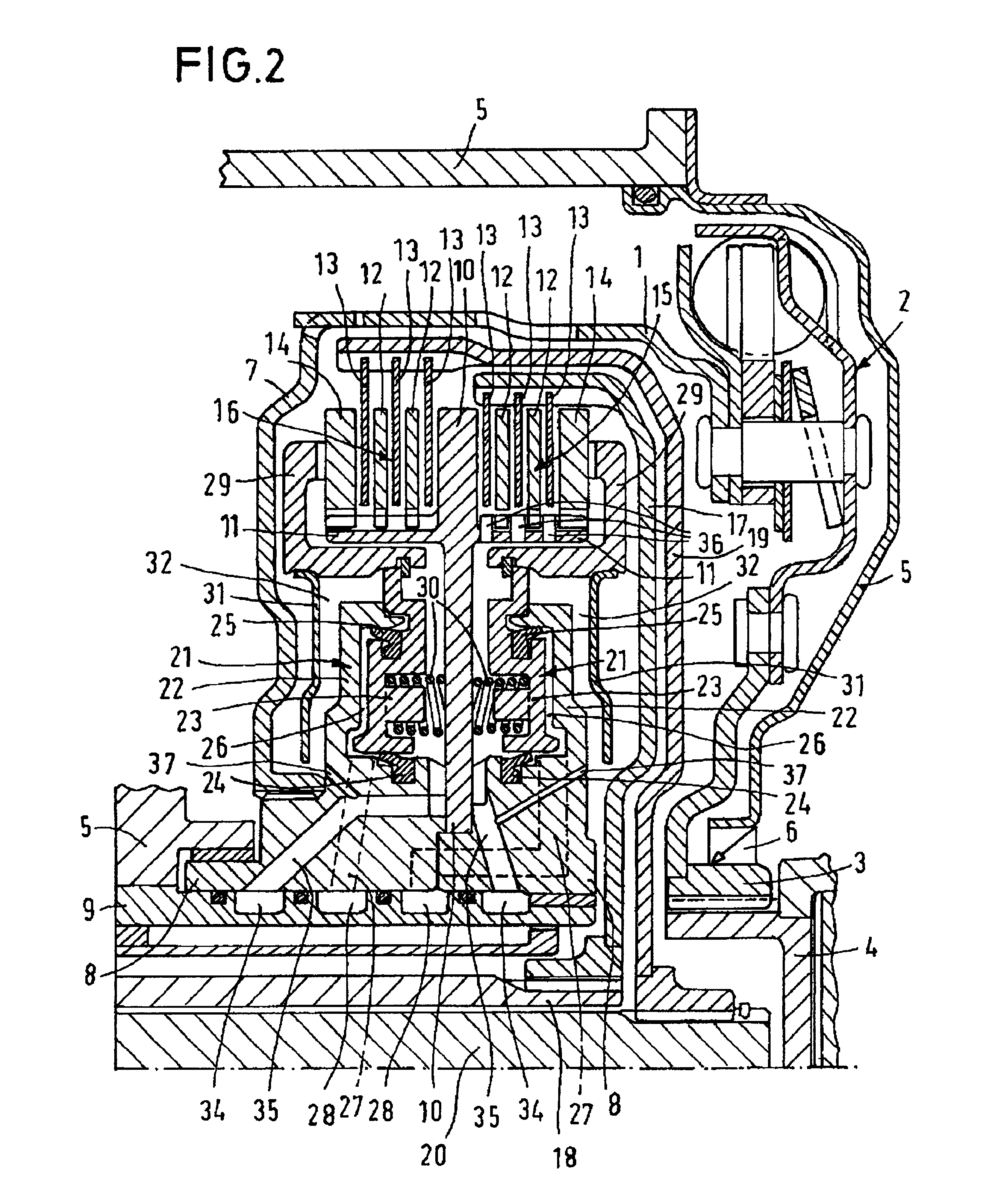
[0024]The twin clutch shown in FIG. 1 has the clutch housing 1, which is connected in a rotationally fixed manner to the drive shaft 4 of an engine (not shown) at the clutch flange 3 by means of the torsional damper unit 2. A shaft sealing ring 6 is arranged between the clutch flange 4 and the transmission housing 5. On the side facing away from the engine, the twin clutch has a clutch-housing cover 7, which connects the clutch housing 1 to the clutch hub 8 in a rotationally fixed manner, the clutch hub 8 being divided into two for reasons connected with assembly.

[0025]The clutch hub 8 is arranged rotatably on the clutch shaft 9 firmly connected to the transmission housing. The purpose of the clutch shaft 9, apart from providing rotary support for the clutch hub 8 and hence for the entire twin clutch, is furthermore to supply oil to the twin clutch, this taking place via the fixed connection between the clutch shaft 9 and the transmission housing 5.

[0026]The clutch web 10 firmly con...


PUM


Abstract

The invention relates to a hydraulic twin clutch for a transmission with two transmission input shafts, preferably for a power-shift transmission in motor vehicles, with concentric arrangement of the two transmission input shafts, a driven clutch housing, two hydraulically actuated clutches with friction disks and annular piston-cylinder units, the first clutch connecting the clutch housing selectably to the first transmission input shaft and the second clutch connecting the clutch housing selectably to the second transmission input shaft. It is distinguished by the fact that the two clutches are arranged adjacent one another, separated by a clutch web firmly connected to the clutch housing, and the two piston-cylinder units provided for the actuation of the clutch are likewise arranged adjacent one another and separated by the clutch web, between the clutches and the transmission input shafts, on a smaller diameter than the clutches. The essential advantages are compact construction combined with high torque capacity and the possibility of achieving complete compensation of the centrifugal-force-dependent pressures in the working chambers through the provision of a compensating chamber.

Description

BACKGROUND OF THE INVENTION[0001]The invention relates to a hydraulic twin clutch for a transmission with two transmission input shafts, preferably for a power-shift transmission in motor vehicles, with concentric arrangement of the two transmission input shafts, a driven clutch housing, two hydraulically actuated clutches with friction disks and annular piston-cylinder units, the first clutch connecting the clutch housing selectably to the first transmission input shaft and the second clutch connecting the clutch housing selectably to the second transmission input shaft.DESCRIPTION OF THE PRIOR ART[0002]DE 3819702 has disclosed a twin clutch of the generic type described in the preamble. The clutch housing is made up of a left-hand cover plate and side plate, a right-hand cover plate and side plate and a casing part that connects them. Annular pistons, which can be subjected to hydraulic pressure and actuate the two multi-disk assemblies by means of cylindrical pins resting against...

Claims


Application Information

Patent Timeline
IPC IPC(8): F16D25/10F16D21/00F16D25/00F16D21/06
CPCF16D21/06F16D25/10F16D2021/0607F16D2021/0661Y02T10/76F16D25/0638F16D2021/0692
Inventor HEGERATH, ANDREAS
Owner FORD GLOBAL TECH LLC
Why Eureka
Try Eureka