Drive circuit of ink jet head and driving method of ink jet head

a technology of ink jet head and driving circuit, which is applied in the direction of printing, other printing apparatus, etc., can solve the problems of unstable lowering the cut-off frequency of low-pass filters, and remarkable so as to improve the dullness of terminal voltage waveforms and stabilize the jetting of ink droplets

Inactive Publication Date: 2005-08-16
FUJIFILM BUSINESS INNOVATION CORP
View PDF7 Cites 29 Cited by
  • Summary
  • Abstract
  • Description
  • Claims
  • Application Information

AI Technical Summary

Benefits of technology

[0016]The present invention was made in view of the above mentioned problems of the conventional ink jet printer and has an object to provide an ink jet drive circuit capable of stably jetting ink droplets, by improving dullness of terminal voltage waveforms of piezo-electric actuators due to influence of the low-pass filter by forming a low-pass filter with using electric resistance of a cable existing between power amplifiers and an ink jet head and electrostatic capacitance of the piezo-electric actuators. Another object of the present invention is to provide a drive method of the ink jet head.

Problems solved by technology

The influence of the low-pass filter on the terminal voltage may cause the jetting of ink droplets to be unstable.
However, the larger number of the nozzles are provided the larger total electrostatic capacitance results, so that the cut-off frequency of the low-pass filter is lowered and dullness of the waveform of the terminal voltage becomes more remarkable.
However, since the number of nozzles to be driven simultaneously is changed time to time, there is a problem that the dullness of the waveform varies correspondingly.
However, if the number of nozzles is increased in order to realize a high speed printing, the number of the power amplifiers must be increased, resulting in not only the size of the construction of the printer but also the amount of heat generation are increased much.
Therefore, weight of the carriage becomes large.
On the other hand, in the ink jet printer of the serial type, the carriage must be driven reciprocally, an increase of weight of the carriage may cause vibration during acceleration and deceleration of the reciprocating carriage, resulting in that the image quality is degraded.
However, in order to make the acceleration and deceleration of the carriage slow, a moving distance of the reciprocating carriage becomes long, causing the size of the printer to be increased.

Method used


Image

  • Drive circuit of ink jet head and driving method of ink jet head
  • Drive circuit of ink jet head and driving method of ink jet head
  • Drive circuit of ink jet head and driving method of ink jet head

Examples


Embodiment Construction

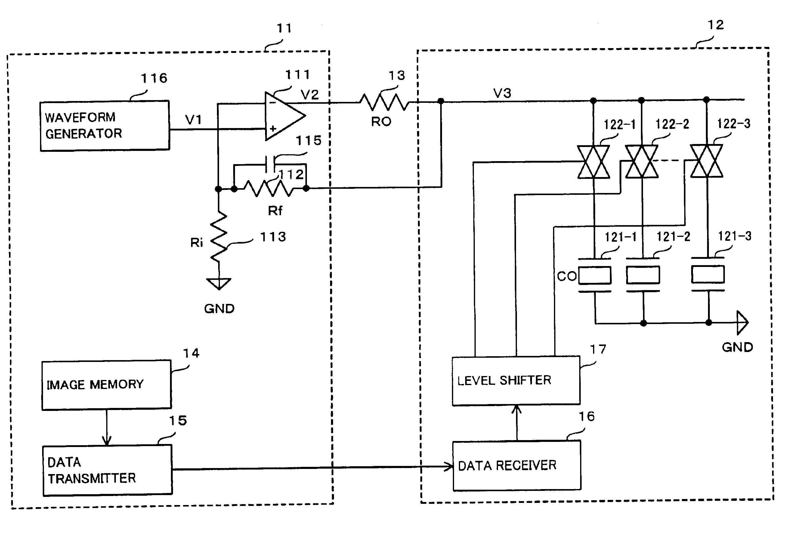
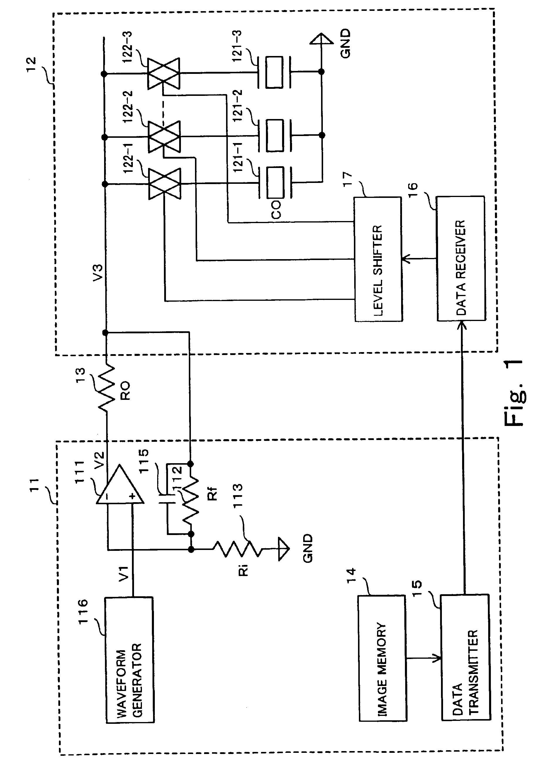
[0032]FIG. 1 is a circuit diagram of an ink jet head drive circuit according to an embodiment of the present invention. In FIG. 1, image memory 14 provided in control circuit board 11 stores a color image data for one printing line to be printed by a serial printer. The color image data stored in image memory 14 and outputted in parallel is converted into a serial data by data transmitter 15 provided in control circuit board 11. The serial data is sent to data receiver 16 mounted on intermediate circuit board 12 arranged on a carriage and reconverted into the parallel data. The latter parallel data is converted into a voltage with which transfer gates 122 can be operated, by level shifter 17, which is provided in intermediate circuit board 12.

[0033]Control circuit board 11 is physically separated from intermediate circuit board 12 and, therefore, a cable for connecting control circuit board 11 to intermediate circuit board 12 is necessary. The use of the serial data in a data transm...


PUM


Abstract

In order to improve dullness of waveform of a drive signal having high slew rate necessary to jet ink droplets, which is caused by an influence of a low-pass filter formed by a resistance of a cable for connecting a power amplifier of an ink jet printer to piezo-electric heads of the printer, which are remote physically from the power amplifier, and a capacitance of the piezo-electric actuators, the ink jet printer includes intermediate circuit board 22 mounted on a carriage, control circuit board 11 having power amplifier 111 and cable 13, wherein a negative feedback loop is provided from inputs of transfer gates mounted on intermediate circuit board 12 through wiring 114 to power amplifier 111 mounted on control circuit board 11.

Description

BACKGROUND OF THE INVENTION[0001]1. Field of the Invention[0002]The present invention relates to a driving circuit of an ink jet head using a piezo-electric actuator and a driving method of an ink jet head and, in particular, the present invention relates to a driving circuit of an ink jet head performing a high quality color image recording by jetting ink droplets and a driving method of the ink jet head.[0003]2. Description of Related Art[0004]In general, a conventional image processing technology for performing highly precise image recording has been of the gray level recording system using the area gray level correction of the dither system. Recently, however, it is requested to print an image having photographic quality at high speed. In order to satisfy such request, it is preferable to improve the image quality by providing a number of nozzles in an image forming device to realize a high speed printing and by controlling the image forming device such that minute ink droplets ...

Claims


Application Information

Patent Timeline
Patent Type & Authority Patents(United States)
IPC IPC(8): B41J2/045B41J2/055
CPCB41J2/04541B41J2/04581
Inventor ISHIZAKI, SUNAO
Owner FUJIFILM BUSINESS INNOVATION CORP
Why Eureka
Try Eureka