
Turbine apparatus and method

a technology of turbines and turbines, applied in the direction of turbines, machines/engines, renewable energy generation, etc., can solve the problems of eccentric load on the tower, the shaft torque, and the addition of further complication to the design, and achieve the effect of being inexpensive in design

Inactive Publication Date: 2005-08-16
RENAISSANCE WIND SYST
View PDF19 Cites 47 Cited by
  • Summary
  • Abstract
  • Description
  • Claims
  • Application Information

AI Technical Summary

Benefits of technology

[0015]In a preferred embodiment, the symmetrical clam shell turbine blades are of a streamlined configuration so as to provide minimal resistance to movement through the fluid stream. In a still further embodiment, the streamlined configuration is in the form of a teardrop shape with a larger leading-edge and a tapered trailing edge. In another embodiment, an adjustable clam shell turbine blade regulating system is provided for regulating the operation of the coordinating system. In a still further embodiment, a rotational velocity governor is provided wherein the load imposed is matched to the requirements of the turbine apparatus so as to act as a governor to restrict turbine apparatus rotational velocity to an optimum range.

Problems solved by technology

This drag differential results in a torque about the shaft and the cups rotate about the shaft due to this torque.
Furthermore, this tower is constrained to be of a structural, vertical cantilevered design, since guy wires would interfere with the rotation of the wind turbine blades.
These turbines also create an eccentric load on the tower adding further complication to their design.
These designs result in significant weight which must be supported by the tower, kept in balance, and allowed to turn as the wind changes direction.
These requirements severely limit the altitude above the earth's surface that such wind turbines can be operated.
Another major limitation of present-day turbine technology is the required configuration of the individual turbine blades.
Current optimizations of these conflicting variables result in blade configurations that are at or near critical values in each category of variable and severely limit the range of operating environment that current turbines may safely experience.
This device utilizes fabric vanes because of weight considerations, thereby making it inappropriate for high wind velocity environments.
In summary, drawbacks to the turbines known in the art, and in particular to wind turbines known in the art, include the necessity for lightweight, and therefor fragile, construction and the resultant inability to take advantage of the vastly more productive high wind velocity environments.
Further, except for rudimentary string / cord devices, no coordination between wind vanes exists so as to enable controlled opening and closing of vanes in all wind conditions and no coordination of the multiple wind vanes is provided at all.
Still further, prior art devices must be stopped when winds exceed design limits or when gusty wind conditions exist.

Method used


Image

  • Turbine apparatus and method
  • Turbine apparatus and method
  • Turbine apparatus and method

Examples


Embodiment Construction

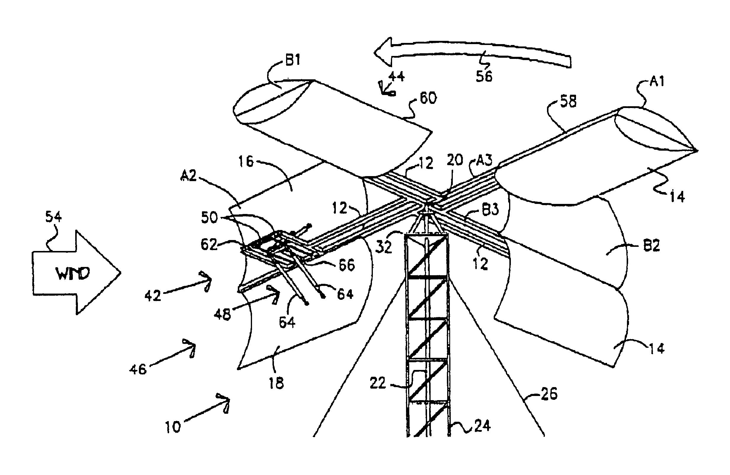
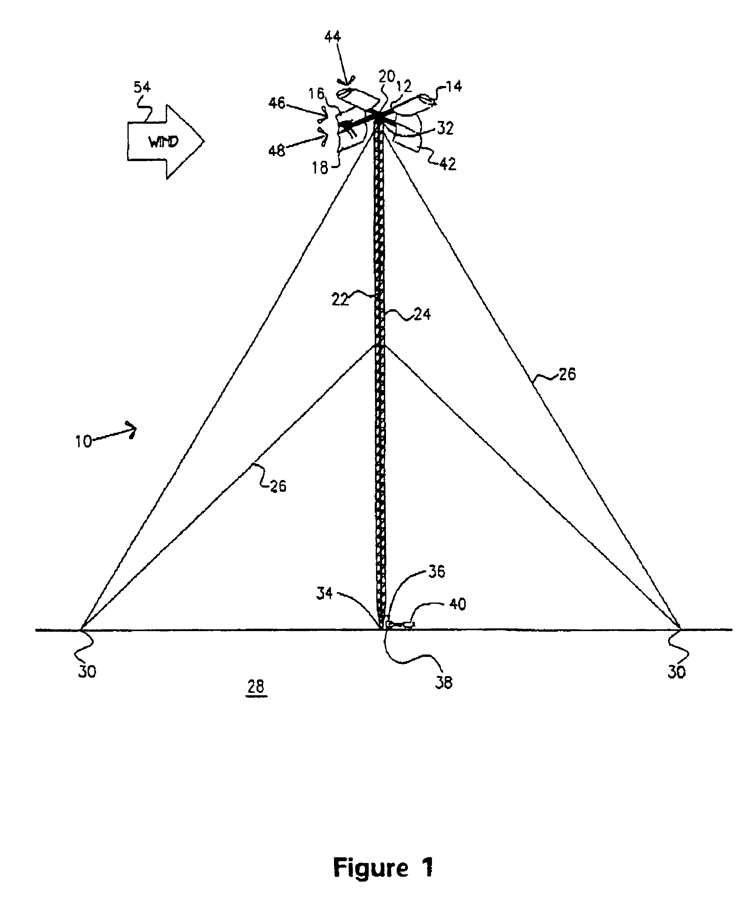
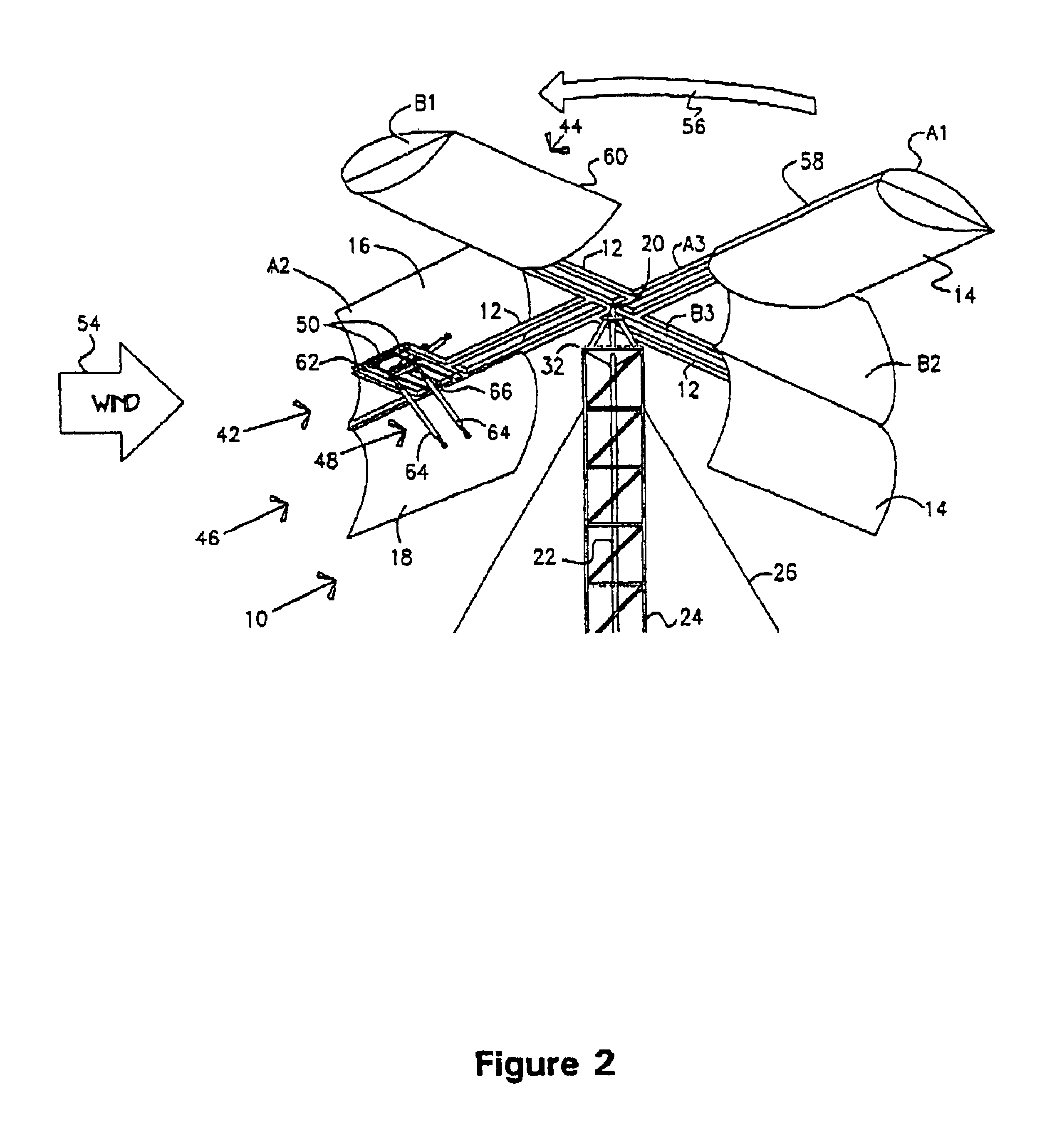
[0025]The preferred embodiment of the present invention is illustrated by way of example in FIGS. 1-7. With specific reference to FIG. 1, turbine apparatus 10 according to an embodiment of the present invention includes torque arm 12 and a pair of, preferably symmetrical clam shell, turbine blades 14. Turbine blades 14 include upper half 16 and lower half 18 which, when in the closed position, present a streamlined aerodynamic shape to the fluid. That is, the halves 16 and 18 are attached to the torque arm 12 on the inside of the halves such that the connections are covered with the aerodynamic shape when closed leaving the exterior free and unencumbered, as will be discussed more fully hereafter. Further, in a preferred embodiment, upper half 16 and lower half 18 of clam shell turbine blades 14 are symmetrical, each half mirroring the other.

[0026]As shown in FIG. 1, a pair of torque arms 12 support two pairs of oppositely positioned turbine blades 14, according to a preferred embod...


PUM


Abstract

A turbine system (10) for capturing energy from a fluid stream includes a torque arm (12). At least a pair of, preferably symmetrical clam shell, turbine blades (14) with the upper (16) and lower (18) halves are oppositely connected to the torque arm (12). A coordinating system (46) is connected to the symmetrical clam shell turbine blades (14). The coordinating system (46) further comprises a first system (48) and second system (52). The first system (48) is connected to control and regulate opening and closing of the upper (16) and lower (18) halves of each individual clam shell turbine blade (14). The second system (52) is connected between each pair of the symmetrical clam shell turbine blades (14) so that as one clam shell turbine blade (14) closes the opposite clam shell turbine blade (14) is forced open.

Description

CROSS REFERENCE TO RELATED U.S. APPLICATION[0001]This Patent Application is a continuation of U.S. patent application Ser. No. 10 / 217,722, filed Aug. 13, 2002 now U.S. Pat. No. 6,682,302, that Patent Application a Continuation-in-Part of U.S. Patent Application Ser. No. 09 / 813,423, filed Mar. 20, 2001 (now abandoned). Applicant hereby claims the benefit of each of the above-referenced Patent Applications and, by this reference, incorporates herein the entire disclosures of those Patent Applications.TECHNICAL FIELD OF THE INVENTION[0002]This invention relates to an improved turbine apparatus and method. In particular, this invention relates to a turbine apparatus for capturing energy from a fluid stream. Further, this invention relates to a wind turbine apparatus.BACKGROUND OF THE INVENTION[0003]A wide variety of turbine devices have been developed in order to remove energy from a flowing stream of fluid. Ancient watermills and windmills attest to man's age-old quest to ease the burd...

Claims


Application Information

Patent Timeline
IPC IPC(8): F03D3/06F03D3/00F03D7/06F03D11/00F03D11/04
CPCF03D3/068F05B2210/16F05B2260/76F05B2270/604Y02E10/74
Inventor NOBLE, JAMES D.
Owner RENAISSANCE WIND SYST
Learn More