Magnetic random access memory designs with patterned and stabilized magnetic shields

a random access and memory design technology, applied in the field of magnetic tunnel junctions, can solve the problems of adverse effect on the storage and reading of data, uncontrollable edge-fields, and large size associations, and achieve the effects of reducing edge effects, small, but non-zero, magnetic moment, and reducing probability

Inactive Publication Date: 2005-08-16
HEADWAY TECH INC
View PDF11 Cites 38 Cited by
  • Summary
  • Abstract
  • Description
  • Claims
  • Application Information

AI Technical Summary

Benefits of technology

[0006]In order for the MTJ MRAM device to be competitive with other forms of DRAM, it is necessary that the MTJ be made very small, typically of sub-micron dimension. Parkin et al. (U. S. Pat. No. 6,166,948) notes that sub-micron dimensions are needed to be competitive with DRAM memories in the range of 10-100 Mbit capacities. Parkin also notes that such small sizes are associated with significant problems, particularly super-paramagnetism, which is the spontaneous thermal fluctuation of magnetization produced by in samples of ferromagnetic material too small to have sufficient magnetic anisotropy (a measure of the ability of a sample to maintain a given magnetization direction). Another size-related problem results from non-uniform and uncontrollable edge-fields produced by shape-anisotropy (a property of non-circular samples). These edge fields result in a large degree from randomly oriented magnetization vectors that form at the edges of the MTJ cells. These orientations have a tendency to curl back towards the magnetization vector of the body of the cell in an effort to minimize the magnetic energy of the cell. Such edge effects are also associated with uncompensated magnetic poles that form at the cell edges. As the cell size decreases, these edge fields become relatively more important than the magnetization of the body of the cell and have an adverse effect on the storage and reading of data. Although such shape-anisotropies, when of sufficient magnitude, reduce the disadvantageous effects of super-paramagnetism, they have the negative effect of requiring high currents to change the magnetization direction of the MTJ for the purpose of storing data. To counteract these edge effects, Shi et al. (U.S. Pat. No. 5,757,695) teaches the formation of an ellipsoidal MTJ cell wherein the magnetization vectors are aligned along the length (major axis) of the cell and which do not present variously oriented edge domains, high fields and poles at the ends of the element.
[0007]MTJ devices have been fabricated in several configurations, one type comprising a free ferromagnetic layer separated from a fixed (or pinned) layer. In such a configuration, the MTJ has data stored in it by causing the magnetization of its free layer to be either parallel or antiparallel to that of the pinned layer. The pinned layer may itself be a composite layer formed of two ferromagnetic layers held in an antiparallel magnetization configuration by some form of magnetic coupling so that it presents a zero or negligible net magnetic moment to the MTJ. Such an arrangement is advantageous in reducing edge effects due to anisotropies. Parkin, cited above, teaches an improved MTJ cell utilizing a free layer that comprises two ferromagnetic layers that are coupled by their dipolar fields in an antiparallel magnetization configuration to produce a small, but non-zero, magnetic moment. When written on by an external applied magnetic field, the two magnetic moments switch directions simultaneously so that the net magnetic moment of the free layer switches direction relative to the pinned layer. In addition, Gallagher et al. (U.S. Pat. No. 5,650,958) teaches the formation of an MTJ device suitable for use in an MRAM array wherein the device comprises a free ferromagnetic layer and a pinned ferromagnetic layer which is pinned by interfacial exchange with an antiferromagnetic layer. Gallagher et al. (U.S. Pat. No. 5,841,692) also teaches the formation of an MTJ device having free and fixed layers wherein the fixed layer is formed as a sandwich of antiferromagnetically coupled ferromagnetic layers. Further, Shi et al. (U.S. Pat. No. 5,959,880) teach the formation of a low aspect ratio MTJ device in which two layers of magnetoresistive material are separated by electrically insulating material.
[0008]It is undesirable for MTJ devices to have excessive magnetic coupling between adjacent magnetic layers of neighboring devices or even within the same device as this coupling must be overcome when writing on the device. As noted above, edge anisotropies are one source of undesirable coupling. Koch et al. (U.S. Pat. No. 6,005,800) deal with the problem that results when writing to one specific cell also affects the magnetization directions of adjacent cells that are not being addressed. Koch teaches the formation of cells with two shapes, which are mirror images of each other. The cells are arranged in a checkerboard pattern, so that a cell of one shape is surrounded by cells of the other shape. Since neighboring cells thereby have their preferred magnetization vectors oriented differently, there is a reduced probability that writing to one cell type will affect the magnetization of the other type.
[0009]As has been discussed, many of the problems associated with the construction of MRAM arrays are related to the shapes of the cells. Cell shapes of present designs are typically single element rectangle, elliptical or lozenge. Chen et al. (U.S. Pat. No. 5,917,749) provides a rectangular multi-layered MTJ cell comprising two rectangular magnetic layers magnetized in parallel directions along an easy axis corresponding to a direction of magnetic anisotropy and separated by a non-magnetic layer.
[0010]Any irregularities of these shapes, defects at their edges produced during their formation, or uncompensated poles of variable strength, will result in coercivity fluctuations distributed throughout the array. It is the object of the present invention to control the problem of undesirable edge effects and non-uniform array coercivity more effectively than is done in the prior art by providing magnetic shields between arrangements of cells within an MRAM array. These shields serve several purposes, including providing pole compensation for edge poles of cell elements, shielding cells from the effects of external magnetic fields and shielding the magnetizations of individual cells from the effects of nearby cells. The use of shields to partially surround MTJ cells is not unknown in the prior art. Gill et al. (U.S. Pat. No. 6,219,212 B1) provide an MTJ device for use as an MRAM cell or as a magnetic field sensor in a magnetic disk drive, in which magnetic material layers disposed above and below the MTJ device. The shields also act as current leads for the MTJ device. It is evident from the topology of the shielding layers that they are not intended to shield one such MTJ device from coplanar adjacent MTJ devices. Furthermore, it is also evident from the shield topology that they are not intended to cancel uncompensated poles formed at the edges of the magnetic free layer of the MTJ device.SUMMARY OF THE INVENTION
[0011]A first object of this invention is to provide an MRAM array of MTJ cells wherein said devices are magnetically shielded from each other and from extraneous external magnetic fields.

Problems solved by technology

Parkin also notes that such small sizes are associated with significant problems, particularly super-paramagnetism, which is the spontaneous thermal fluctuation of magnetization produced by in samples of ferromagnetic material too small to have sufficient magnetic anisotropy (a measure of the ability of a sample to maintain a given magnetization direction).
Another size-related problem results from non-uniform and uncontrollable edge-fields produced by shape-anisotropy (a property of non-circular samples).
As the cell size decreases, these edge fields become relatively more important than the magnetization of the body of the cell and have an adverse effect on the storage and reading of data.
Although such shape-anisotropies, when of sufficient magnitude, reduce the disadvantageous effects of super-paramagnetism, they have the negative effect of requiring high currents to change the magnetization direction of the MTJ for the purpose of storing data.
It is undesirable for MTJ devices to have excessive magnetic coupling between adjacent magnetic layers of neighboring devices or even within the same device as this coupling must be overcome when writing on the device.
As noted above, edge anisotropies are one source of undesirable coupling.
As has been discussed, many of the problems associated with the construction of MRAM arrays are related to the shapes of the cells.
Any irregularities of these shapes, defects at their edges produced during their formation, or uncompensated poles of variable strength, will result in coercivity fluctuations distributed throughout the array.
Furthermore, it is also evident from the shield topology that they are not intended to cancel uncompensated poles formed at the edges of the magnetic free layer of the MTJ device.

Method used


Image

  • Magnetic random access memory designs with patterned and stabilized magnetic shields
  • Magnetic random access memory designs with patterned and stabilized magnetic shields
  • Magnetic random access memory designs with patterned and stabilized magnetic shields

Examples


Embodiment Construction

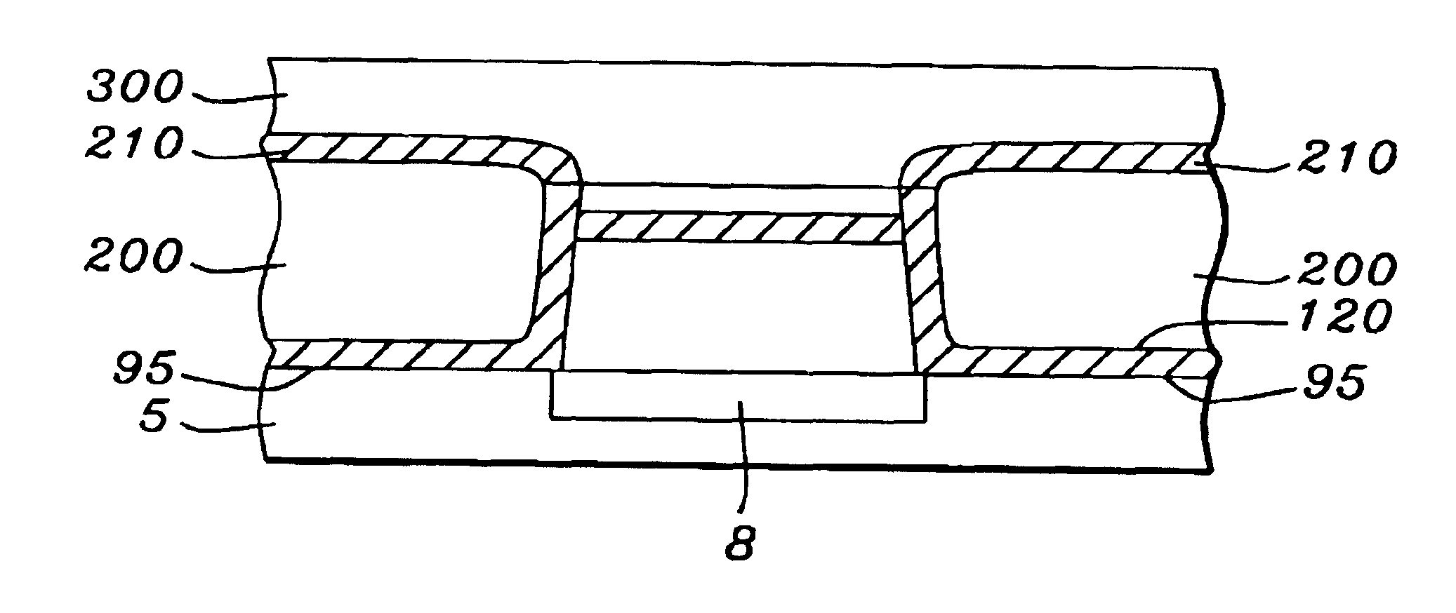
[0024]The preferred embodiment of the present invention teaches a method of forming a shielded MRAM array of MTJ cells, said cells being substantially surrounded by and electrically insulated from a formation of ferromagnetic magnetic shields which conform to the shape of the MTJ cells and which may be stabilized by the formation of additional layers of antiferromagnetic and permanent magnetic materials. The magnetic shields compensate magnetic poles which would ordinarily form at the edges of the MTJ cells and shield the cells from undesired magnetic fields.

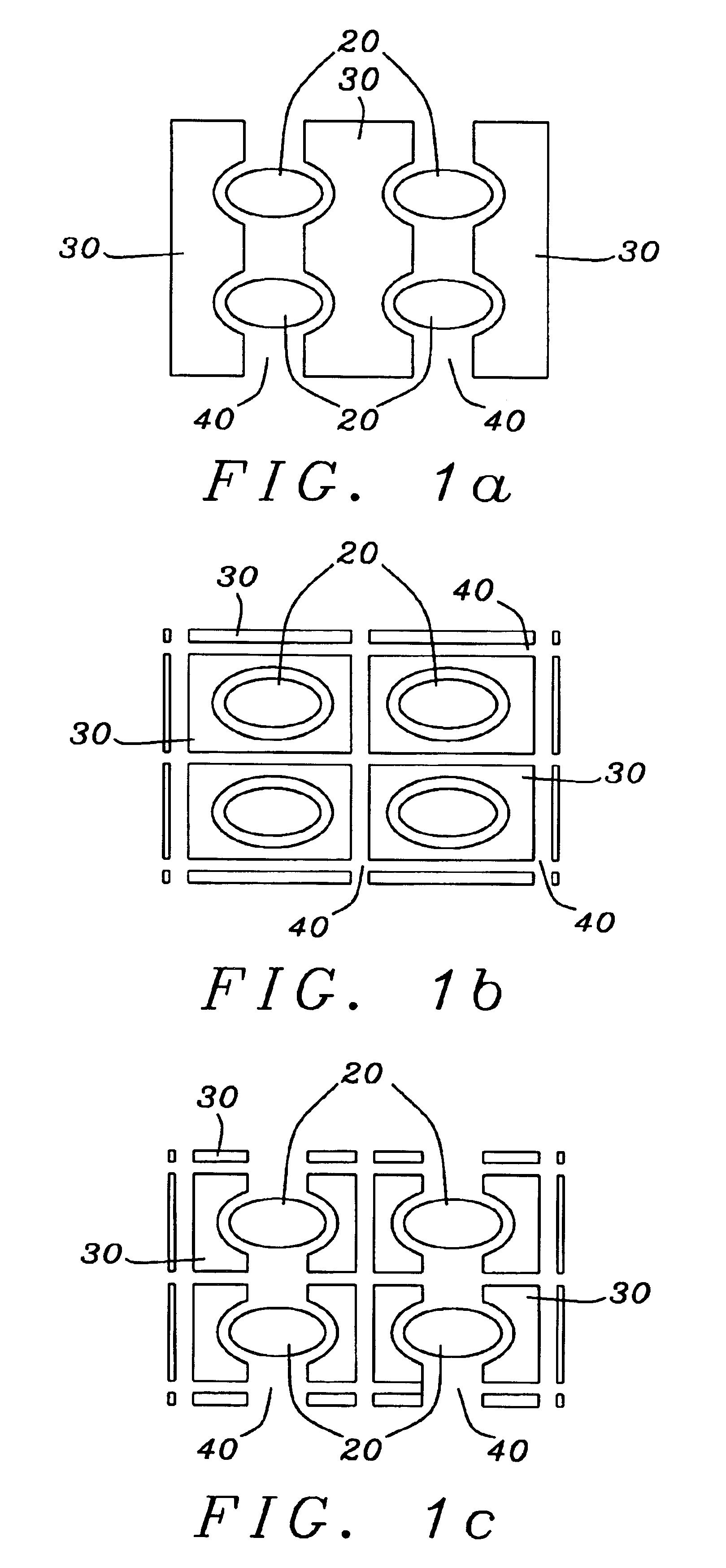
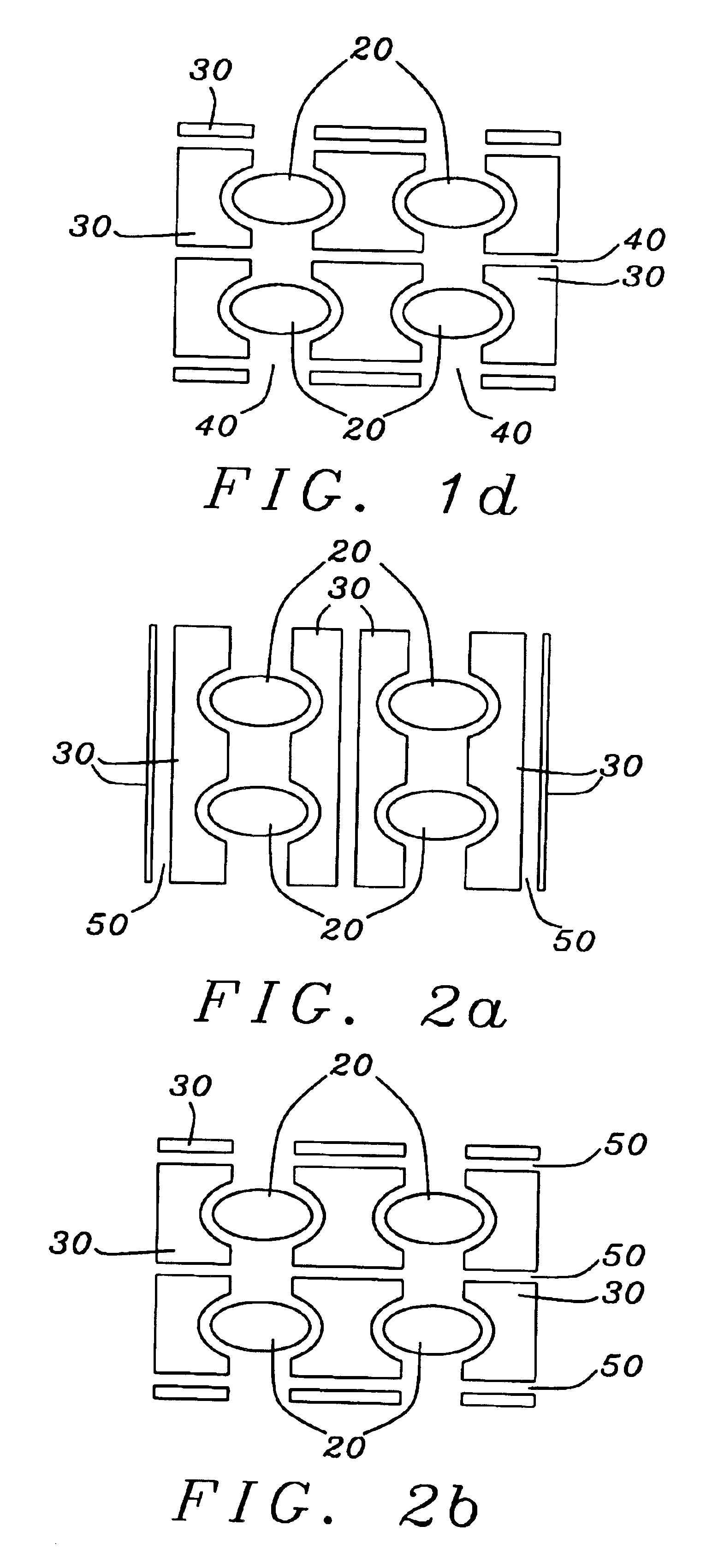
[0025]Referring first to FIGS. 1a-1d, there is shown schematic overhead diagrams of an array of elliptical MTJ cells (20) surrounded by different shield (30) and gap (40) patterns. Any of these designs would meet the objects of the present invention and it is clear that other patterns may be equally appropriate if they satisfy the design criteria. The choice of MTJ cells which are substantially identical in their size and ellipt...


PUM

PropertyMeasurementUnit
thicknessaaaaaaaaaa
thicknessaaaaaaaaaa
thicknessaaaaaaaaaa

Abstract

A magnetic tunneling junction (MTJ) memory cell and an MRAM array of such cells, is shielded by magnetic shields of ferromagnetic material or by ferromagnetic shields that are stabilized by patterned layers of antiferromagnetic material or permanent magnetic material. The ferromagnetic portions of the shields surround the MTJ cells substantially conformally and thereby can compensate the poles of the free layers of MTJ cells of various geometric cross-sectional shapes and also protect the cells from the adverse effects of extraneous fields. The additional antiferromagnetic and permanent magnetic materials stabilize the shields by exchange or direct coupling.

Description

BACKGROUND OF THE INVENTION[0001]1. Field of the Invention[0002]This invention relates to the use of magnetic tunnel junctions (MTJ) as storage elements (cells) in non-volatile magnetic memory cell arrays (MRAM). In particular it relates to MRAM arrays of shielded MTJ cells in which the cells have their uncompensated edge poles eliminated by magnetostatic coupling to magnetic shields and, in addition, are shielded from each other and from extraneous external magnetic fields by various forms and configurations of said shields.[0003]2. Description of the Related Art[0004]The magnetic tunnel junction (MTJ) basically comprises two electrodes, which are layers of ferromagnetic material, separated by a tunnel barrier layer, which is a thin layer of insulating material. The tunnel barrier layer must be sufficiently thin so that there is a probability for charge carriers (typically electrons) to cross the layer by means of quantum mechanical tunneling. The tunneling probability is spin depe...

Claims


Application Information

Patent Timeline
Patent Type & Authority Patents(United States)
IPC IPC(8): H01F10/00G11C11/15H01F10/32H01F10/12H01L21/00G11C11/02H01L43/00H01L27/105H01F10/16H01L43/10H01L43/08H01L21/8246H01L27/115H01L27/22H01L29/78H01L43/12
CPCG11C11/15H01L27/222H01L43/08H01L43/12H10B61/00H10N50/10H10N50/01
Inventor MIN, TAIWANG, PO KANG
Owner HEADWAY TECH INC
Why Eureka
Try Eureka