Traction motor fault detection system

a technology for fault detection and traction motors, applied in the direction of motor/generator/converter stopper, dynamo-electric converter control, instruments, etc., can solve the problems of time-consuming process and complicated identification of faulted motors within the truck assembly, and achieve the effect of reducing the mean time for finding

Inactive Publication Date: 2005-08-16
ELECTRO-MOTIVE DIESEL
View PDF9 Cites 22 Cited by
  • Summary
  • Abstract
  • Description
  • Claims
  • Application Information

AI Technical Summary

Benefits of technology

[0003]The traction motor fault detection system according to the present invention concerns a diagnostic system that identifies faulted motors without disconnection of the traction motor cables. The system detects motor ground faults (shorts, arcing, leakage) and phase to phas...

Problems solved by technology

The milking machine splits each inverter phase output cable into a set of parallel motor cables which gre...

Method used


Image

  • Traction motor fault detection system
  • Traction motor fault detection system
  • Traction motor fault detection system

Examples


Embodiment Construction

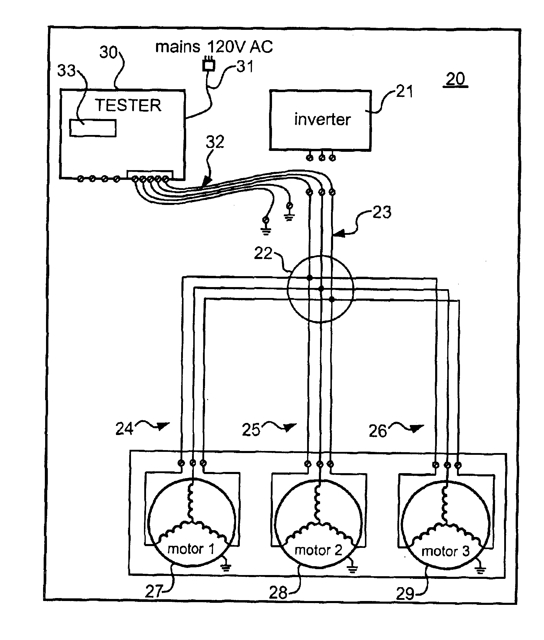
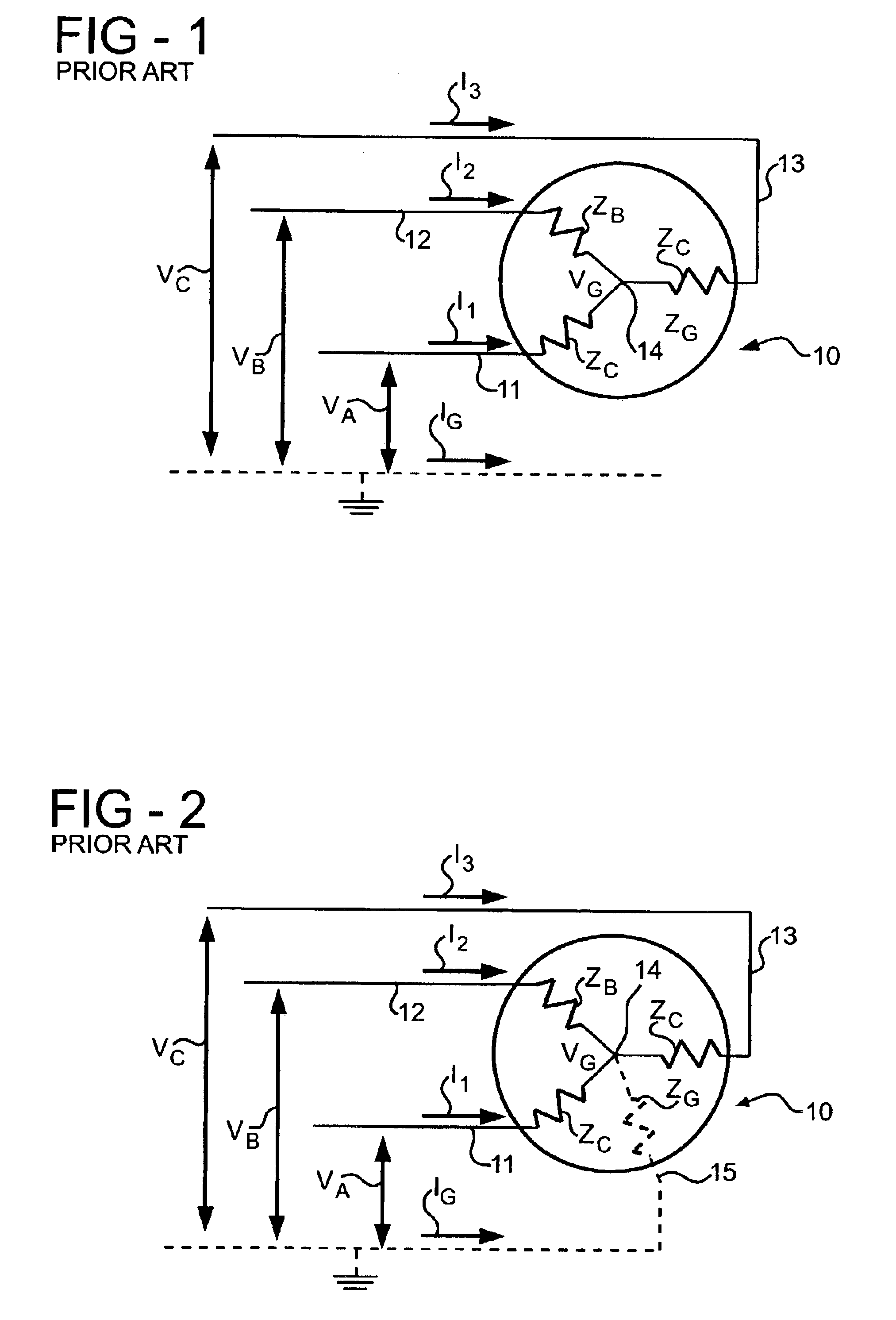
[0016]FIG. 1 is a schematic diagram of a typical three phase electric motor 10 having winding terminals 11, 12 and 13. Three stator windings ZA, ZB and ZC are Y-connected with one end connected to a center node 14 and opposite ends connected to the terminals 11, 12 and 13 respectively. Under normal operating conditions, i.e., no fault, the motor 10 can be described as a three terminal, two port device. When the motor 10 has an internal ground fault, it becomes a four terminal, three port device as shown in FIG. 2 wherein the ground fault is represented as an impedance ZG connected between the center node 14 and a fourth terminal 15. Absent a ground fault, a motor with an internal phase short between any two of the terminals 11, 12 and 13, can be described as a two terminal, one port device.

[0017]The condition of the motor 10 can be evaluated by connecting a selected pair of the terminals 11, 12 and 13 to ground and applying a known test voltage to the remaining terminal. For example...


PUM


Abstract

A method of detecting faults in a traction motor installation having a plurality of AC traction motors powered from a common power source, each of the traction motors being connected by associated motor cables to a cable junction and the common power source being connected to the cable junction by main cables, includes disconnecting the power source from the main cables and performing initial short circuit to ground, short circuit between phases and leakage to ground tests on the traction motors through the main cables. When a fault is detected by the initial tests, at least one detailed test is performed by applying a predetermined voltage to the main cables and sensing current flow in the motor cables connected to each of the motors. The detailed test is one of a detail short circuit to ground test, a detail short circuit phase to phase test, and a detail leakage to ground test.

Description

BACKGROUND OF THE INVENTION[0001]The present invention relates generally to a method for testing electric motors and, in particular, to a system for detecting faults in multiple AC traction motor installations.[0002]The present AC traction motor architecture employed in electric locomotive traction devices or trucks connects each phase output from an inverter to each traction motor through an intermediate wiring harness, commonly referred to as the “milking machine”. The milking machine splits each inverter phase output cable into a set of parallel motor cables which greatly complicates the identification of faulted motors within a truck assembly. Historically, under worst case conditions, one has to disassemble all parallel motor connections in order to locate one motor that had developed a fault. This is a time consuming process.SUMMARY OF THE INVENTION[0003]The traction motor fault detection system according to the present invention concerns a diagnostic system that identifies fa...

Claims


Application Information

Patent Timeline
IPC IPC(8): G01R31/34G01R31/00
CPCG01R31/34G01R31/005
Inventor SAUNDERS, JOHN M.MADSEN, JOHN E.
Owner ELECTRO-MOTIVE DIESEL
Why Eureka
Try Eureka