

Voltage level converter device
- Summary
- Abstract
- Description
- Claims
- Application Information
AI Technical Summary
Benefits of technology
Problems solved by technology
Method used
Image

Examples
Embodiment Construction
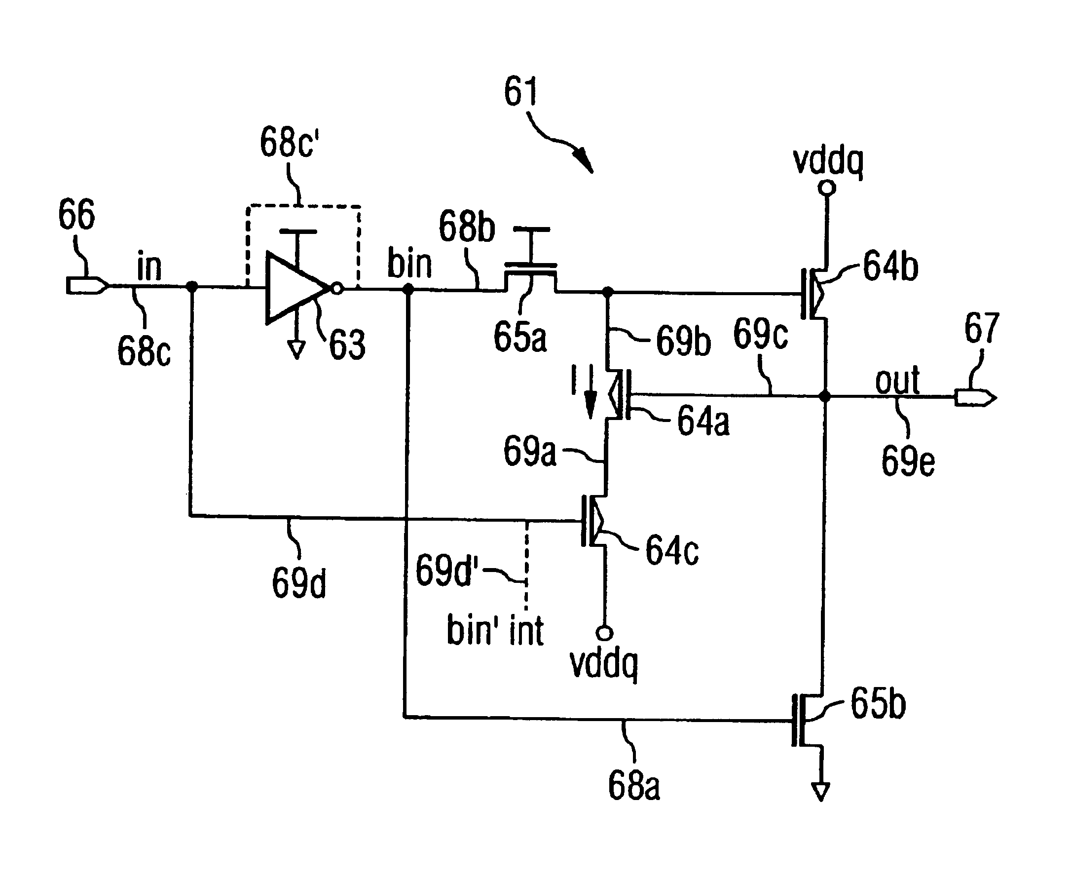
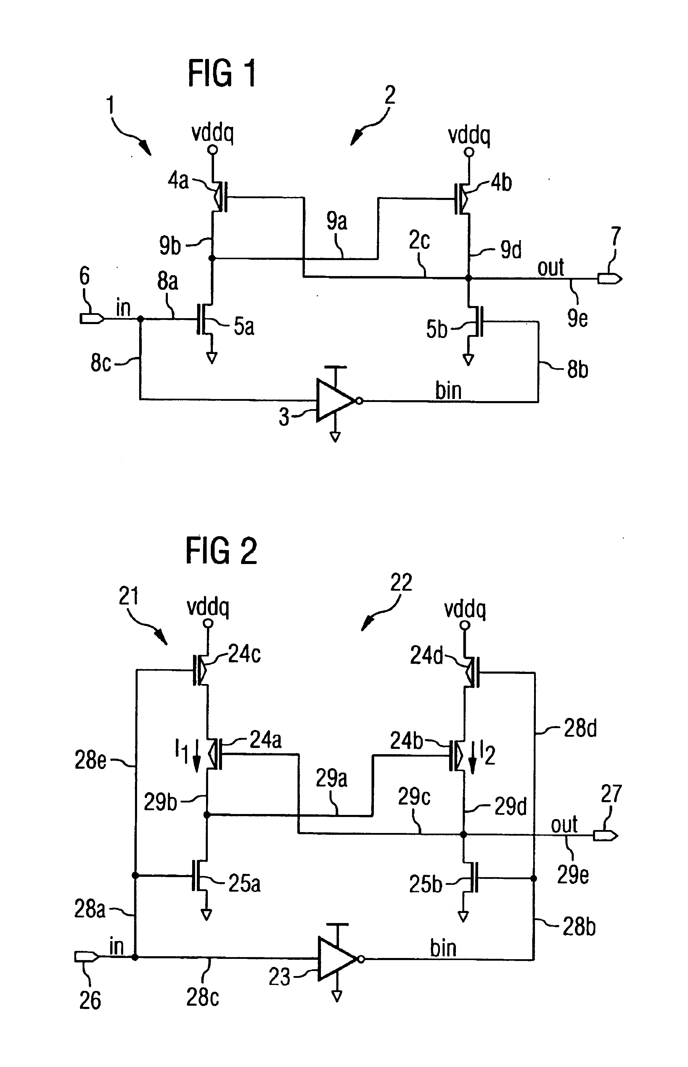
[0025]In FIG. 1, a schematic representation of a circuit configuration of a first example of a state-of-the-art voltage converter 1 is shown. The voltage converter 1 is built into a DRAM memory component, for instance one based on CMOS technology. The converter serves to convert the internal voltage level (vint) used inside the memory component to an external voltage level (vddq) used outside the memory component, whereby the internally used voltage level (vint) is lower than the externally used voltage level (vddq). The internal voltage level (vint) can for example amount to between 1.5 V and 2.0 V (here for instance 1.5 V or 1.8 V), and the external voltage level (vddq) for instance to between 2.5 V and 3.5 V (here for instance 2.5 V or 2.9 V).
[0026]As shown in FIG. 1, the voltage converter 1 has an amplifier circuit 2, having four cross-connected transistors 4a, 4b, 5a, 5b, i.e. a first and a second p-channel field effect transistor 4a, 4b (here: two p-channel MOSFETs 4a, 4b), as...
PUM
 Abstract
Description
Claims
Application Information