Optical fiber array with lenses

a technology of optical fiber array and optical fiber, applied in the field of optical fiber array with lenses, can solve the problems of difficult to make an optical fiber array, large number of optical fibers must be used for communication involving an enormous amount of information, and large number of optical fibers to achieve the effect of facilitating connection operations

Inactive Publication Date: 2005-08-16
HITACHI METALS LTD
View PDF16 Cites 26 Cited by
  • Summary
  • Abstract
  • Description
  • Claims
  • Application Information

AI Technical Summary

Benefits of technology

[0010]It is thus an object of the present invention to provide an optical fiber array with lenses which allows the interval between optic...

Problems solved by technology

However, a large number of optical fibers must be used for communication involving an enormous amount of information that cannot be processed by the wavelength division multiplex method.
Consequently, a propagation loss occurs when the optical signal is connected to a light beam path such as another opti...

Method used


Image

  • Optical fiber array with lenses
  • Optical fiber array with lenses
  • Optical fiber array with lenses

Examples


example 1

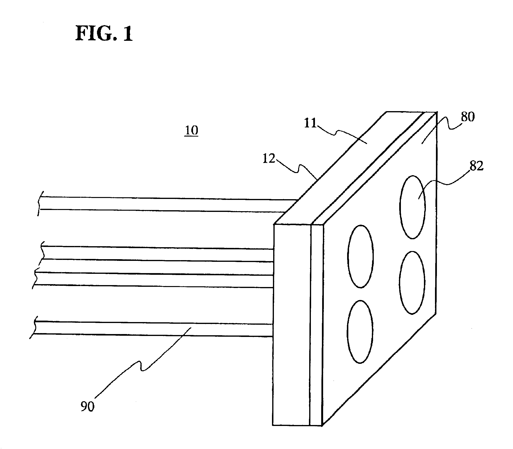
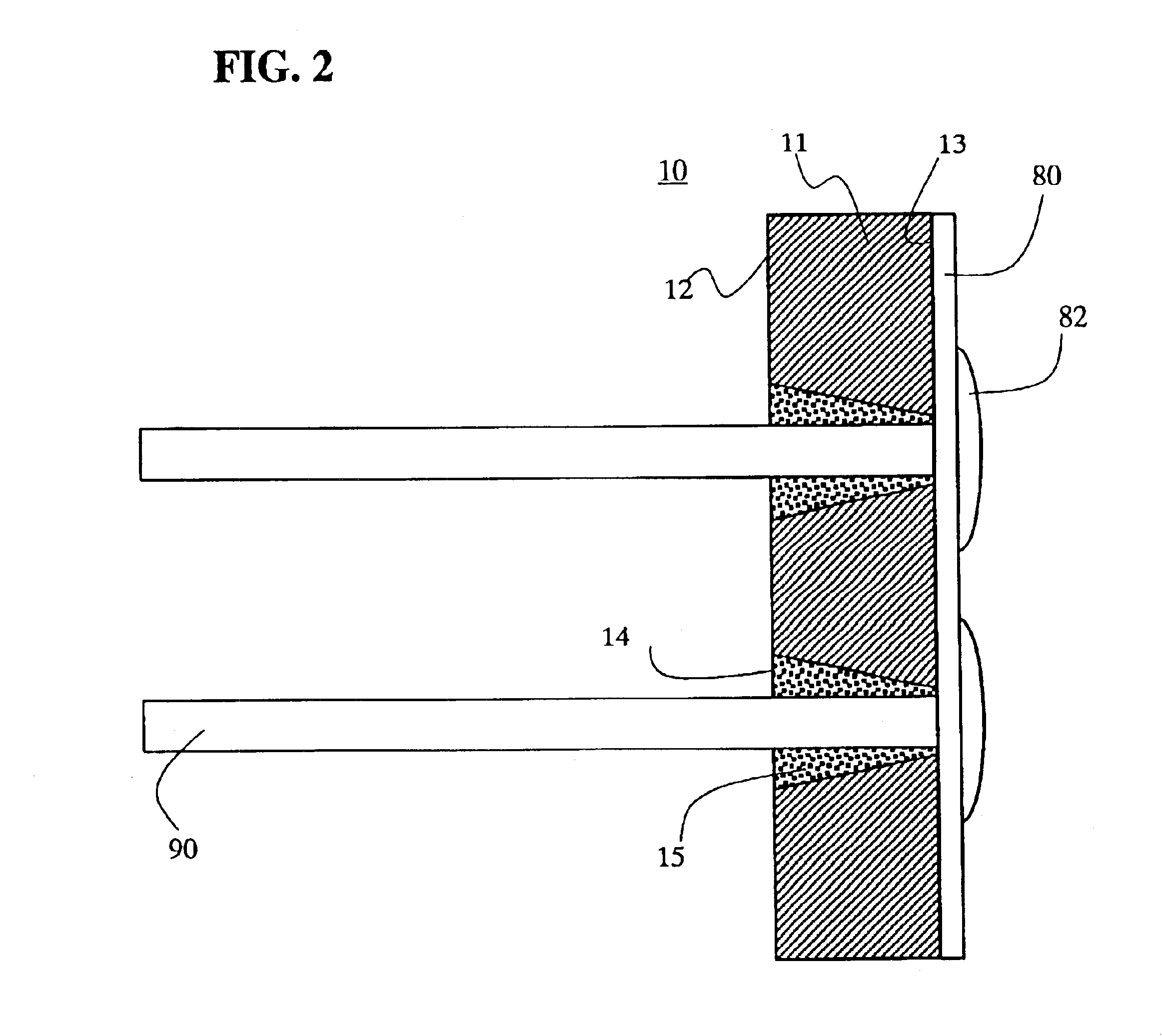
[0031]With reference to FIGS. 1 and 2, description will be given of an optical fiber array with lenses 10 according to EXAMPLE 1 of the present invention. FIG. 1 is a perspective view, viewed on a collimator lens side, of the optical fiber array with lenses 10. FIG. 2 is a cross section of the optical fiber array with lenses 10 along the line of tapered through-holes and optical fibers of the optical fiber array. The optical fiber array with lenses 10 has four optical fibers with lenses 90 arranged in two stages and two rows. The arrangement pitch in the vertical direction of the optical fibers with lenses is different from that in the horizontal direction of these fibers. A base plate 11 has a first end surface 12 and a second end surface 13 opposite to the first end surface 12. The first end surface 12 is parallel with the second end surface 13. The base plate 11 has openings 14 arranged on the first end surface 12 and through-holes 15 each opened from the corresponding opening 14...

example 2

[0039]With reference to FIG. 3, description will be given of an optical fiber array with lenses 20 according to EXAMPLE 2 of the present invention. FIG. 3 is a cross section of the optical fiber array with lenses along the line of tapered through-holes and optical fibers of the optical fiber array. In FIG. 3, the same parts as those in FIGS. 1 and 2 for EXAMPLE 1 are denoted by the same reference numerals. The optical fibers 90 are each inserted into a corresponding tapered through-hole 25 and are each then secured in the tapered through-hole using a refraction index matching agent 28. Both a second end surface 23 of a base plate 21 and an end surface 84 of a microlens array 80′ are polished so that an angle θ is about 8 degrees with the optical axis of the optical fiber 90. Then, an end surface 84 of the microlens array 80′ is joined to the second end surface 23 of the base plate 21 using a refraction index matching agent. Since the tip surface of each optical fiber is tilted at an...

example 3

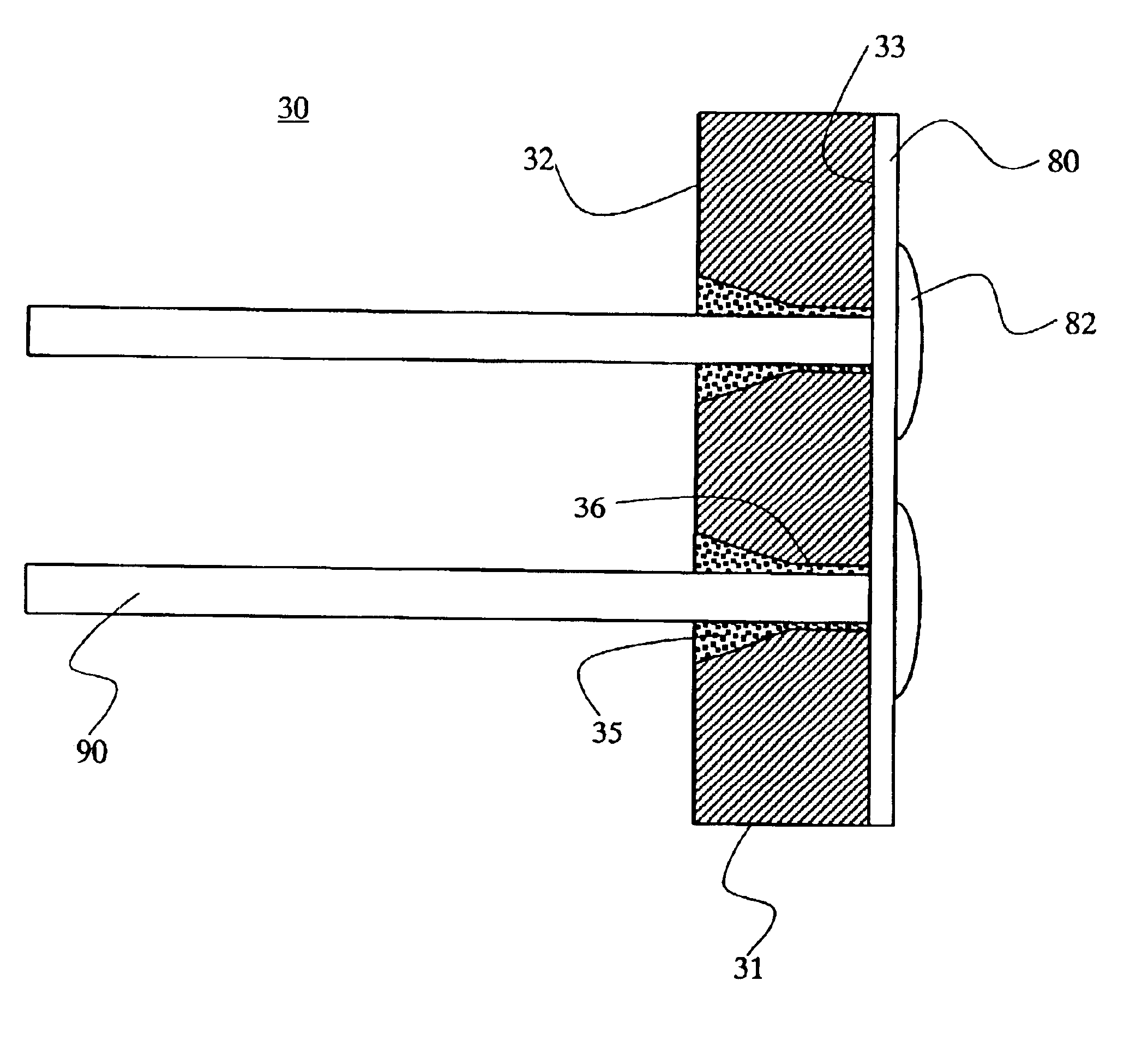
[0040]With reference to FIG. 4, description will be given of an optical fiber array with lenses 30 according to EXAMPLE 3 of the present invention. FIG. 4 is a cross section of the optical fiber array with lenses along the line of tapered through-holes and optical fibers of the optical fiber array. In FIG. 4, the same parts as those in FIGS. 1 and 2 for EXAMPLE 1 are denoted by the same reference numerals. Through-holes are each formed from a corresponding one of the openings arranged on a first end surface 32 of a base plate 31, toward a second end surface 33. The through-hole is composed of a tapered hole 35 having a tapered inside wall extending toward the second end surface and a parallel hole 36 having a parallel inside wall formed between an end of the tapered inside wall and the opening on the second end surface 33 and having a uniform diameter. The microlens array 80, which has the plurality of collimator lenses 82, is secured on the second end surface 33 of the base plate 3...


PUM


Abstract

An optical fiber array with lenses connected with a plurality of optical fibers is disclosed, enabling to be manufactured to meet the optical fiber end intervals to the terminal intervals of an optical device to be connected and having an improved efficiency in connection operation. The optical fiber array comprises a base plate having a first end surface and a second end surface opposite to the first end surface, a plurality of optical fibers having a tip surface inserted and secured in each of the holes opened on the base plate, and a plurality of collimator lenses installed on the second end surface facing the tip surfaces of the optical fiber. Each hole has a tapered inside wall having a diameter gradually decreasing from an opening on the first end surface of the base plate toward the second end surface and a parallel inside wall continuing from the tapered inside wall end. In the hole, a refraction index matching agent is preferably filled in between the tip surface of the optical fiber and the collimator lens. The optical fiber array is designed so as to match the optical axis pitches of the optical fibers and collimator lenses to the terminal pitches of the optical device to be connected.

Description

BACKGROUND OF THE INVENTION[0001]1. Field of the Invention[0002]The present invention relates to an optical fiber array with lenses used in a field of optical communication.[0003]2. Description of the Related Art[0004]In recent years, technological innovation has been significant in information communication. To accommodate an increased communication speed and an increased amount of information communicated resulting from the spread of an Internet, communication has been shifting from the reliance on electric signals to the use of optical signals. More and more traditional cables, which were used as essential elements of many networks, have been replaced with optical ones because information from various relay points is gathered at the cables. Accordingly, the processing speed has been substantially improved. However, the communication between optical cables and user terminals is expected to be reviewed because there have been more and more exacting demands for the establishment of ...

Claims


Application Information

Patent Timeline
IPC IPC(8): G02B6/36G02B6/32G02B6/35
CPCG02B6/32G02B6/327G02B6/3582G02B6/3672G02B6/3512G02B6/3546G02B6/3644G02B6/3692
Inventor SUZUKI, MASARUAO, MASAHIRO
Owner HITACHI METALS LTD
Why Eureka
Try Eureka