Implantable tissue stimulating device

a tissue stimulation and implantable technology, applied in the field of implantable tissue stimulation devices, can solve the problems of unwanted stimulation of other muscles subjected to the field, and achieve the effect of increasing the electrical field and favorable electric field distribution

Inactive Publication Date: 2005-08-16
ST JUDE MEDICAL
View PDF9 Cites 31 Cited by
  • Summary
  • Abstract
  • Description
  • Claims
  • Application Information

AI Technical Summary

Benefits of technology

[0009]It is an object of the invention to provide a housing for an implantable tissue stimulating device which allows the electric fields, which are generated around the housing and which could cause unwanted muscle stimulation, to be eliminated or at least reduced to a safe level, so the risk of unwanted muscle stimulation is eliminated, and which can be produced in a simpler and more cost-effective manufacturing process.
[0011]The inventive housing for an implantable tissue stimulating device, when implanted, acts as an electrode and shaped so as create low strength electric fields in regions where unwanted stimulation of muscles can occur, without the need top cover portions of the housing with an insulating layer.
[0012]By the arrangement of a curved circumferential first wall section connected to a first wall having a generally flat exterior surface, and a curved circumferential second wall section connected to a second wall having a generally flat exterior surface, where the first wall section has a smaller radius of curvature than the second wall section a favorable electric field distribution around the housing is obtained.
[0013]Roughening the surface or providing the surface with ridges or irregularities can increase the electrical field at the region of the wall facing the skin.

Problems solved by technology

This may, depending on the strength of the field, cause unwanted stimulation of other muscles subjected to the field, e.g. the pectoralis major.
However, it is costly due to the step of the application of the parylene itself and the pre-treatment and after treatment steps.

Method used


Image

  • Implantable tissue stimulating device
  • Implantable tissue stimulating device
  • Implantable tissue stimulating device

Examples


Embodiment Construction

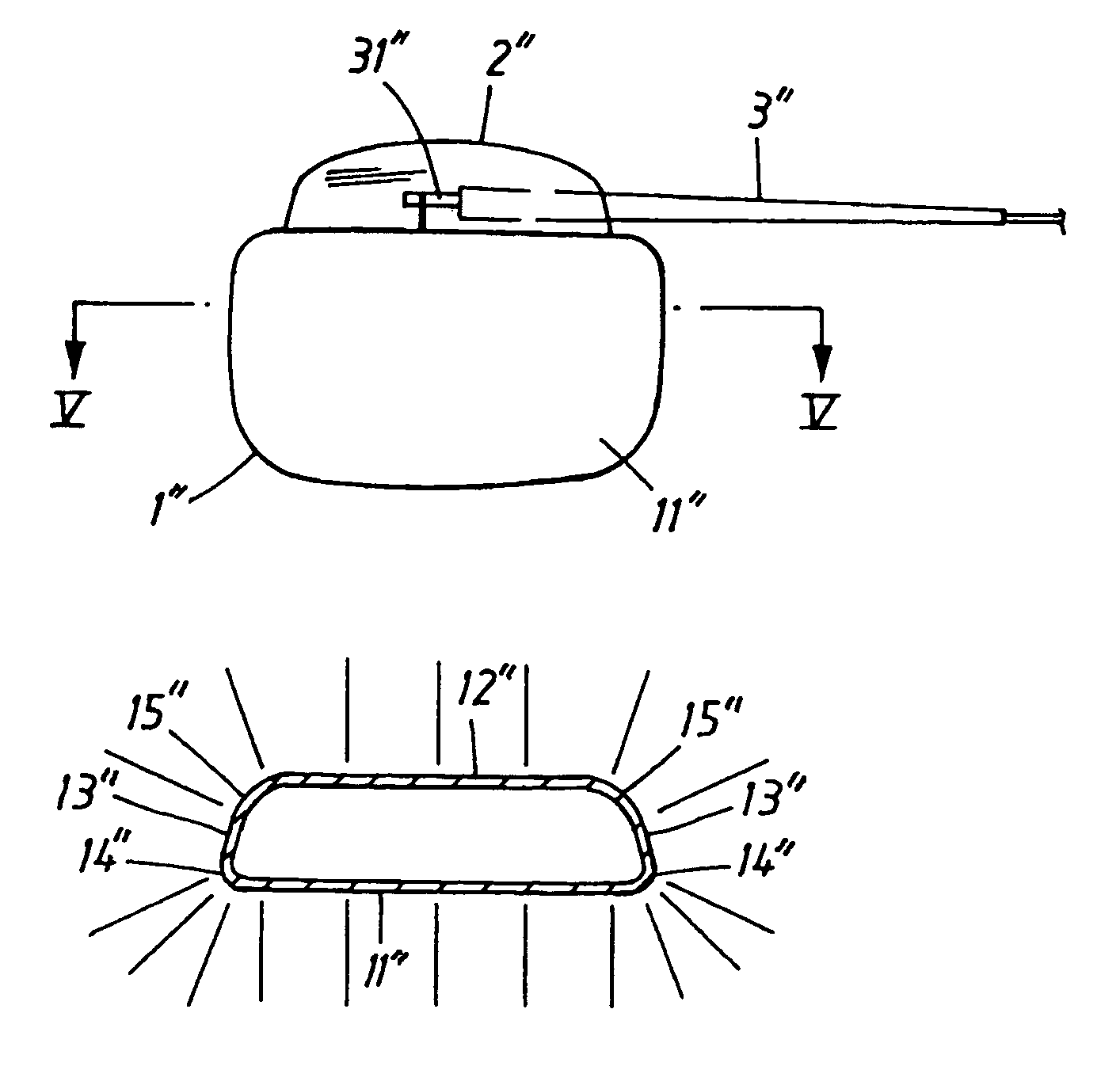
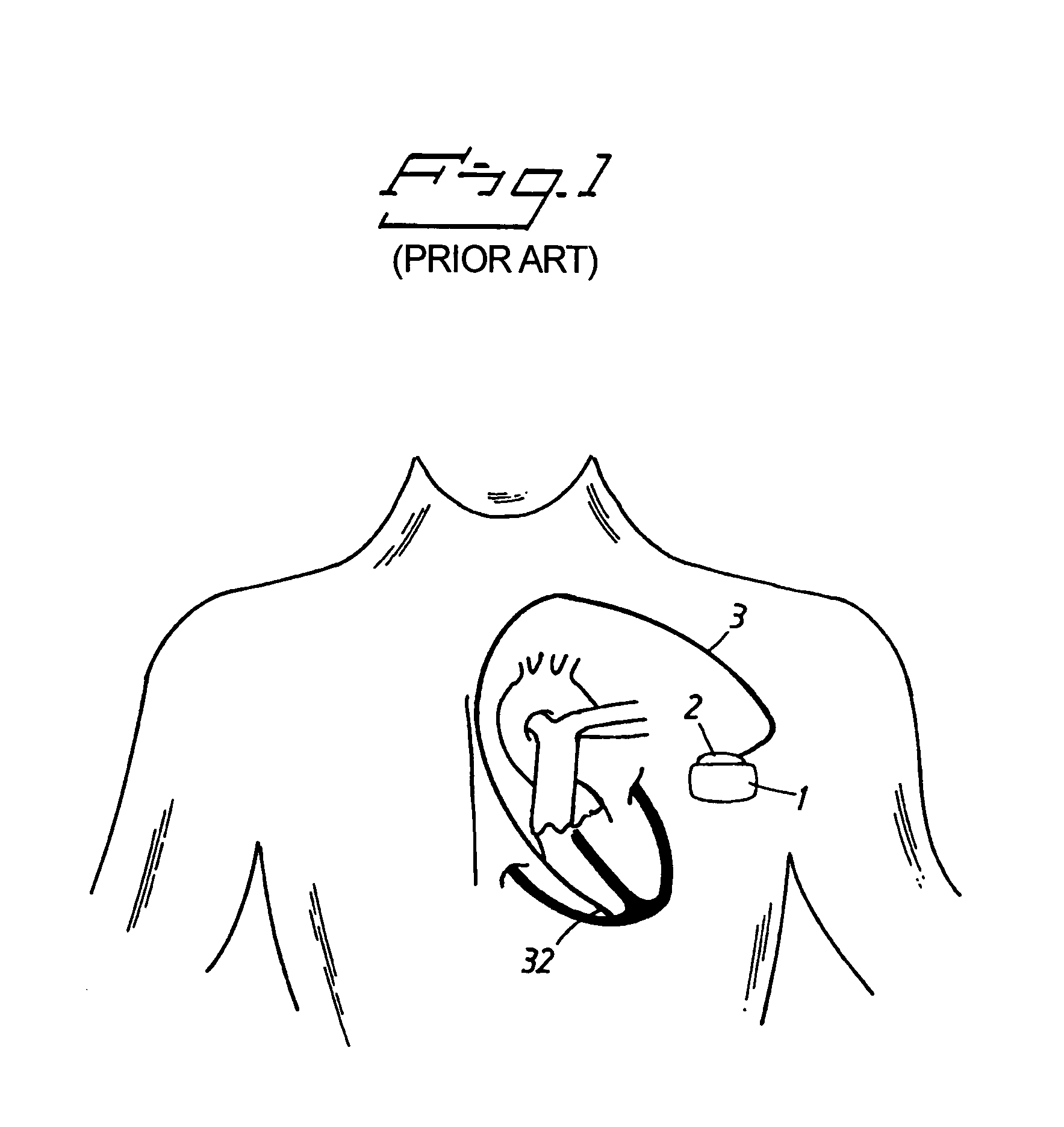
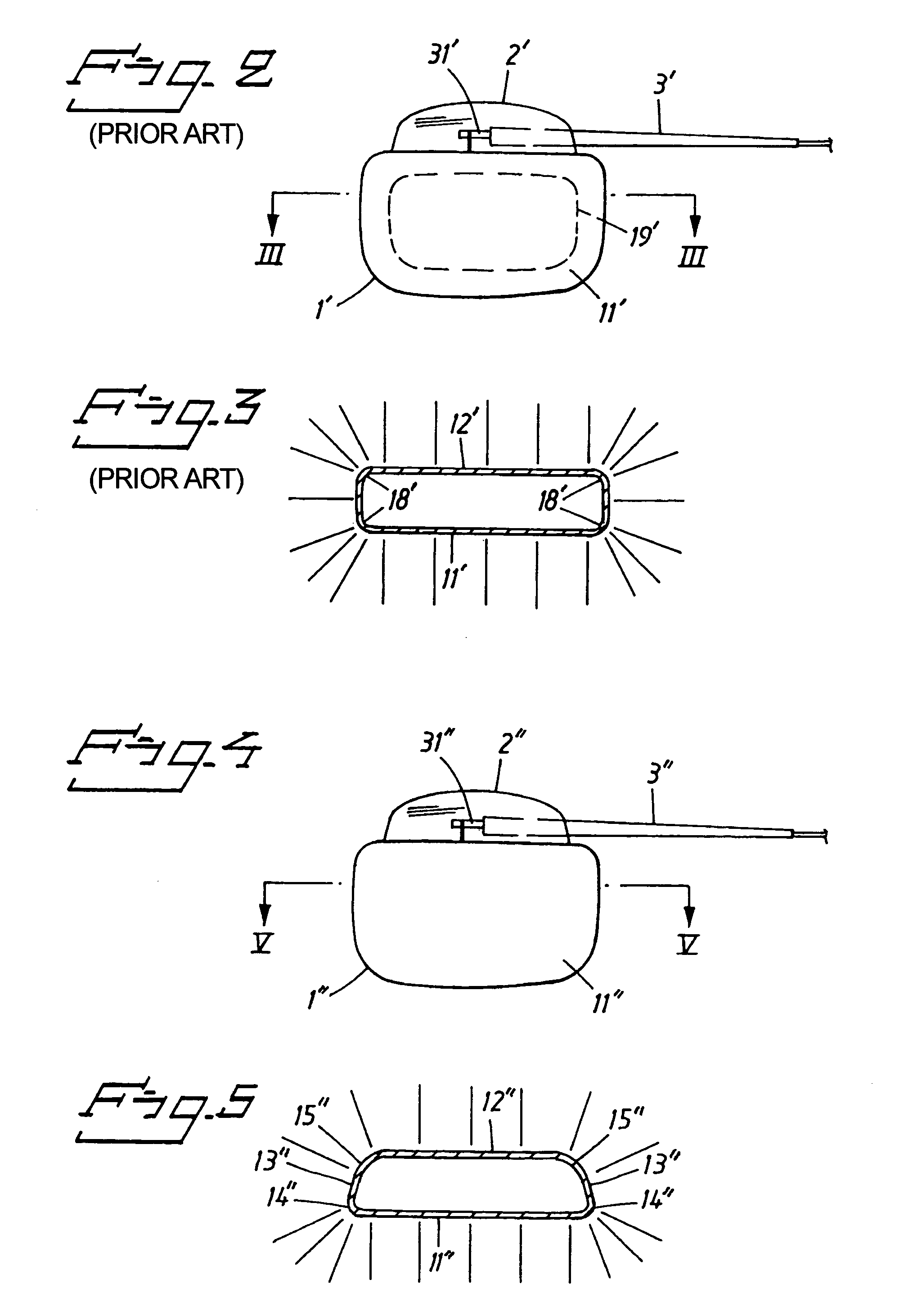
[0023]A conventional placement of a pacemaker implanted in a patient is shown. A housing 1 for a pulse generator is implanted on the left side of the chest. The housing is conductive, made of a bio-compatible material such as titanium, and hermetically sealed against intrusion of body fluids and tissue when implanted. On top of the housing a header 2 is arranged. The header is made of transparent epoxy resin, and is molded onto the housing. The header includes a female portion of an electrical connector coupled to the circuits of the pulse generator. An electrode lead 3 includes at its proximal end a male connector 31 (connector pin, not shown) for electrical connection with said female connector. At the distal end the electrode lead 3 is provided with a stimulation electrode 32, which is located in the heart in electrical contact with the tissue. A stimulation pulse generated by the pulse generator will be applied between the electrode 32 and the housing 1, which also acts as an el...


PUM


Abstract

A housing for an implantable tissue stimulating device is connectable to an electrode lead having an electrode. A portion of the housing also functions as an electrode. The walls of the housing are shaped so that when a voltage is applied between the electrode at the electrode lead, and the housing electrode, the electric field associated with the voltage has a low field strength in regions at which unwanted stimulation of muscles can occur.

Description

BACKGROUND OF THE INVENTION[0001]1. Field of the Invention[0002]The invention relates to a housing for an implantable tissue stimulating device, especially an implantable heart stimulation device.[0003]2. Background of the Invention and Related Art[0004]Heart stimulation devices for human beings, such as pacemakers are usually implanted in the chest, generally on the left side, a short distance below the clavicle or collar bone. The device will then rest between the pectoralis major and the skin. An electrode lead supplies electric pulses to the heart from the device. The electrode lead includes one or more electrodes, a connector at the proximal end of the electrode lead for connection of the lead to the stimulation device conductor(s) between the connector pin and the electrode(s), one of which typically is located at the distal end of the lead and insulation. The electrode lead is typically passed upwardly over the clavicle and is connected to the heart through a vein adjacent to...

Claims


Application Information

Patent Timeline
Patent Type & Authority Patents(United States)
IPC IPC(8): A61N1/372A61N1/375
CPCA61N1/375A61N1/37512
Inventor MAGNUSSON, GUNNAR
Owner ST JUDE MEDICAL
Why Eureka
Try Eureka