
Vehicle electric motor diagnosing apparatus

Active Publication Date: 2005-08-16
NISSAN MOTOR CO LTD
View PDF22 Cites 55 Cited by
  • Summary
  • Abstract
  • Description
  • Claims
  • Application Information

AI Technical Summary

Benefits of technology

[0009]In light of these problems, an object of the present invention is to provide a vehicle drive control apparatus having excellent reliability, and that can rapidly detect a failure in the electric motor and thereby call attention to the need for repair of the electric motor.

Problems solved by technology

As a result, failures may arise such as in the electric motor itself or in disconnections or short circuits in the harness to the electric motor due to vehicle usage conditions, environmental changes, and the like, during that period.
Subsequently, even if an attempt is made to drive the subordinate drive wheels when acceleration slip is generated in the main drive wheels, the electric motor does not operate due to the failure, leading to cases in which the desired acceleration performance and traveling stability unfortunately cannot be obtained.
However, because a counterelectromotive force arises in the electric motor corresponding to the rotational speed thereof, the generated electric power may be inadequate because the voltage of the electric power supplied from the generator to the electric motor may be smaller than the counterelectromotive force of the motor.
If a self-diagnostic of the electric motor is executed at such a time, there may be a problem in that the diagnosis cannot be made reliably because the electric motor is not rotating sufficiently, or there may be a problem in that the discovery of that failure may take time because the diagnosis requires a long time due to the length of time needed for the electric motor to reach a rotational speed at which a diagnosis can be made.

Method used


Image

  • Vehicle electric motor diagnosing apparatus
  • Vehicle electric motor diagnosing apparatus
  • Vehicle electric motor diagnosing apparatus

Examples


first embodiment

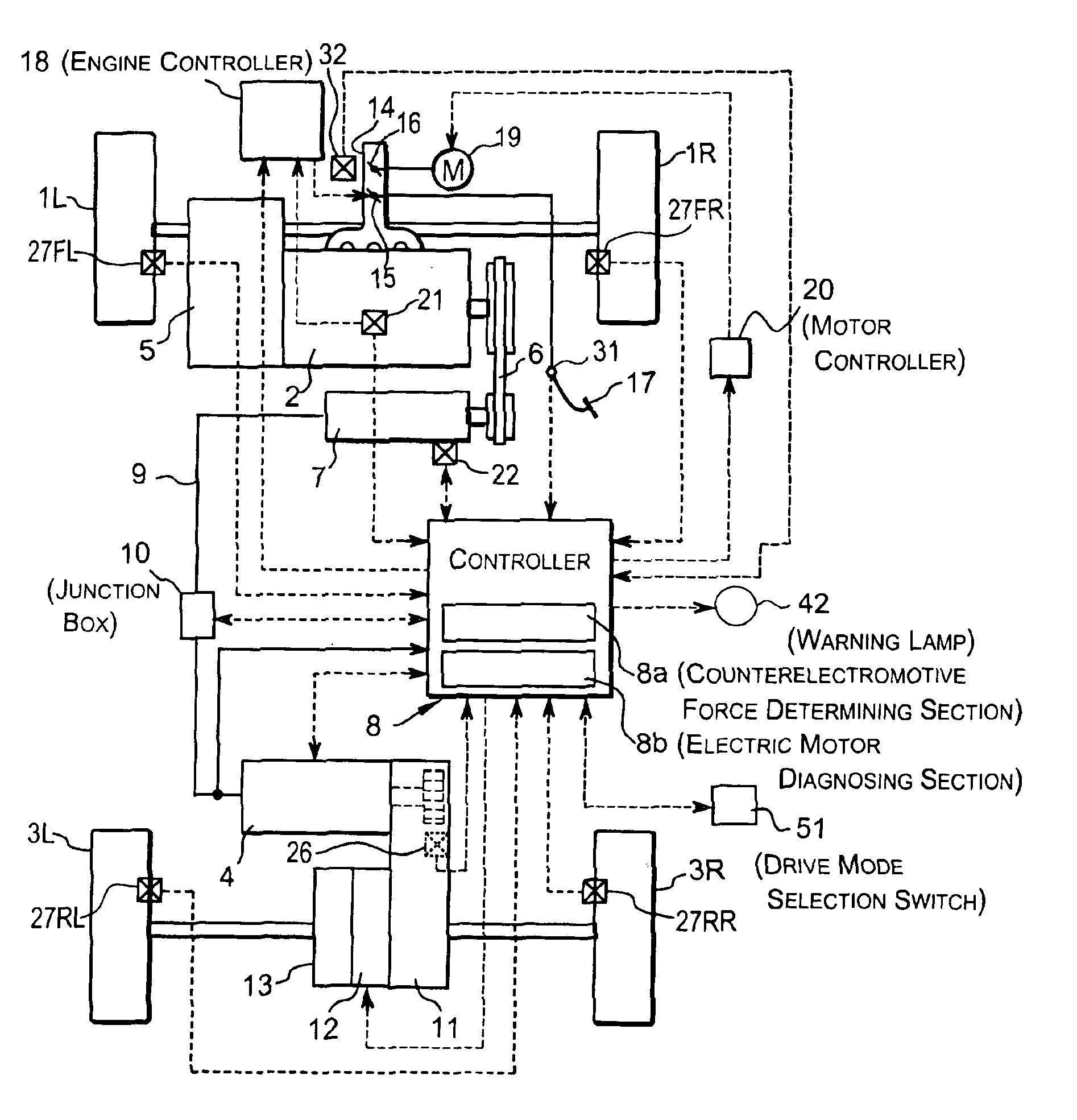
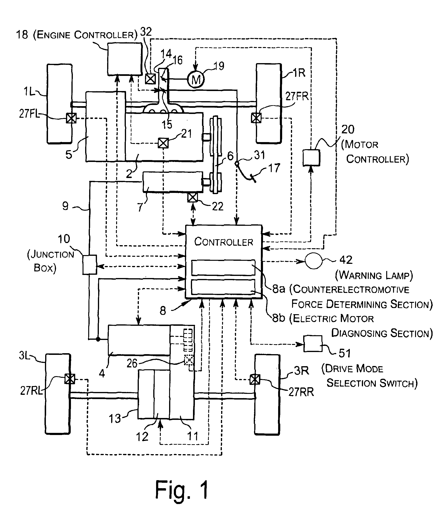
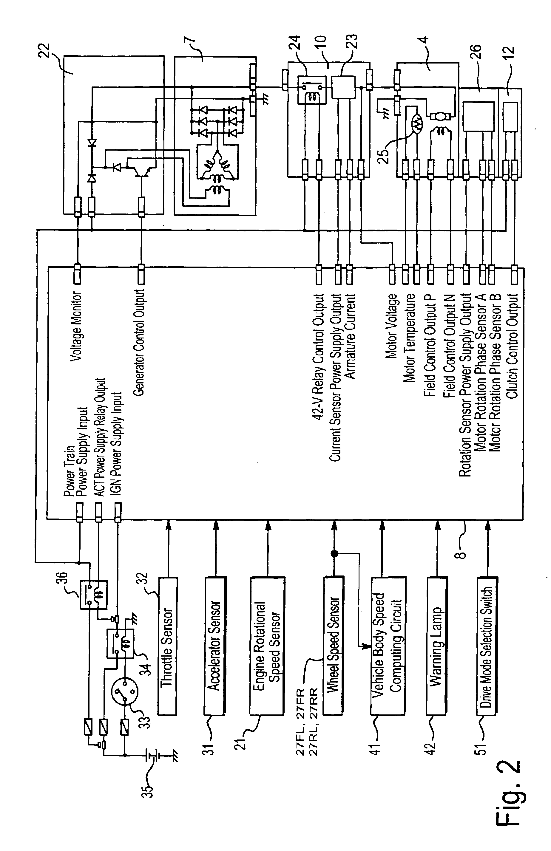
[0031]Referring initially to FIGS. 1 to 5, a vehicle drive control apparatus is illustrated in accordance with a first embodiment of the present invention. FIG. 1 is a schematic view of the main components of the vehicle drive control apparatus. FIG. 2 is control system configuration for the vehicle drive control apparatus. FIG. 3 is a flow chart for explaining the operation of the present embodiment. FIG. 4 is an exemplary time chart according to the present embodiment.

[0032]As seen in FIG. 1, a four wheel drive vehicle is diagrammatically illustrated that is equipped with the vehicle drive control apparatus in accordance with the present invention. As shown in FIG. 1, the vehicle in accordance with this embodiment has left and right front wheels 1L and 1R that are driven by an internal combustion engine or main drive source 2, and left and right rear wheels 3L and 3R that are driven by an electric motor or subordinate drive source 4, which is preferably a direct current (DC) elect...

second embodiment

[0059]Incidentally, as shown in FIG. 5, even if the generated voltage of generator 7 is a voltage generated only by the permanent magnets portion (lower solid line), there is a case in which the counterelectromotive force (broken line) increases when the rotational speed of the electric motor 4 is less than or equal to a predetermined speed (Nm2). In such a case, as shown in the time chart of FIG. 6, if the predetermined speed Nm2 is set to a normal determination threshold value, the generator voltage V (alternator) will exceed the electric motor induced voltage E, and motor rotational speed Nm≧Nm2 will become true, making it an undeniable possibility that the results will be misdetermined as normal, even if the field coil of the generator 7 cannot be controlled due to a failure. Therefore, in the second embodiment according to the present invention, as explained below, in a case where the two-wheel drive fixed mode is selected by the operation of the drive mode selection switch 51 ...

third embodiment

[0067]In addition, as shown in FIG. 10, if the engine rotational speed is low, the rotation of electric motor 4 does not reach the electric motor normal determination threshold value Nm1 because an insufficient amount of power is generated even if the generator control is set on, and it is conceivable that a normal determination cannot be made.

[0068]In the third embodiment of the present invention as explained below, in a case wherein the two-wheel drive fixed mode is selected by the operation of the drive mode selection switch 51 and the engine rotational speed exceeds a predetermined speed, then the controller 8 diagnoses whether the electric motor 4 is operating, by continuing to energize and control the field coil of the generator 7 in a state wherein the clutch 12 is disengaged, and by driving the electric motor 4 for a short period of time.

[0069]FIG. 11 is a flow chart for explaining the operation of the third embodiment. In step S21, the controller 8 reads in the engine rotat...


PUM


Abstract

An electric motor diagnosing apparatus is provided in a vehicle having a generator driven by a drive torque of a drive source, an electric motor driven by electric power supplied from the generator, and a wheel driven by the electric motor. The electric motor diagnosing apparatus comprises a counterelectromotive force determining section and an electric motor diagnosing section. The counterelectromotive force determining section determines whether a voltage of electric power supplied from the generator to the electric motor is greater than an induced voltage of a counterelectromotive force of the electric motor. The electric motor diagnosing section drives the electric motor by controlling the generator to supply the electric power to the electric motor, and determines whether the electric motor is rotating, upon determining that the voltage of the electric power supplied from the generator to the electric motor is greater than the electric motor induced voltage.

Description

BACKGROUND OF THE INVENTION[0001]1. Field of the Invention[0002]The present invention generally relates to a vehicle electric motor diagnosing apparatus. More particularly, the present invention relates to a vehicle electric motor diagnosing apparatus for diagnosing an electric motor that drive a subordinate wheel of a four-wheel drive vehicle.[0003]2. Background Information[0004]An electric motor diagnosing apparatus for a vehicle capable of four-wheel drive is Japanese Laid Open Patent Application No. 2002-218605. The electric motor diagnosing apparatus of this publication is directed to improving acceleration performance and traveling stability. The electric motor diagnosing apparatus of this publication is used in a vehicle having one pair of the front and rear wheels utilized as the main drive wheels, and the other pair of wheels utilized as the subordinate drive wheels. This electric motor diagnosing apparatus achieves its aims by driving the main drive wheels by an internal c...

Claims


Application Information

Patent Timeline
IPC IPC(8): B60L11/02B60K6/04B60K6/00B60K28/16B60W20/00B60K6/44B60K6/52B60K6/54B60L50/10B60L50/16B60W10/08F02D29/02
CPCB60K6/52B60L3/0023B60L3/10B60L11/02B60L11/123B60L11/14B60W10/08H02P9/305B60K6/442B60K1/02Y02T10/642B60K28/16B60L2240/421B60L2240/441B60L2240/461B60L2240/465B60L2250/10B60L2250/16B60W20/00B60W2510/0604B60W2510/0638B60W2510/081B60W2510/244B60W2520/10B60W2520/26B60W2520/28B60W2540/10Y02T10/6217Y02T10/6234Y02T10/6265Y02T10/7077B60L50/10B60L50/61B60L50/16Y02T10/62Y02T10/64Y02T10/7072Y02T10/70B60W2050/143B60W2710/083B60W2050/0001
Inventor SHIMIZU, KOUICHIOHYA, HIROYUKI
Owner NISSAN MOTOR CO LTD
Features
  • Generate Ideas
  • Intellectual Property
  • Life Sciences
  • Materials
  • Tech Scout
  • Unparalleled Data Quality
  • Higher Quality Content
  • 60% Fewer Hallucinations
Learn More