Method for automatically adjusting measuring equipment and device using the same

a technology of automatic adjustment and measuring equipment, applied in the direction of noise figure or signal-to-noise ratio measurement, instruments, code conversion, etc., can solve the problems of impossible measurements, error is sure to occur in the amplification factor for each range of the frequency characteristic switch, and the amplification factor error is sure to occur in the amplification factor for each range of the level range switch. to achieve the effect of reducing the effect of self-nois

Inactive Publication Date: 2005-08-16
RION COMPANY
View PDF5 Cites 6 Cited by
  • Summary
  • Abstract
  • Description
  • Claims
  • Application Information

AI Technical Summary

Benefits of technology

[0031]To accomplish the above object, a first aspect of the present invention provides a method of correcting self-noise when amplifying an output signal from a sensor so as to conform to the sensitivity of the sensor, further processing the amplified signal, and then outputting the processed signal as a measured value, the method comprising calculating a self-noise component from the sensor sensitivity, using this self-noise component as an element to calculate a correction value, and using this correction value to reduce the effects of the self-noise on the measured value.

Problems solved by technology

However, an error is sure to occur in amplification factor for each range of the level range switch owing to differences among resistors constituting amplifiers provided for the respective ranges.
However, an error is sure to occur in amplification factor for each range of the frequency characteristic switch owing to differences among resistors constituting correction circuits provided for the respective ranges.
This makes measurements impossible, resulting in deviation from the measurement range.
Consequently, the operation is not efficient.
Thus, the use of variable resistors may result in instability.
Further, if the acoustic measuring instrument is provided with a level range switch used to select the optimum maximum input level according to the level of an input signal to be measured, then errors in amplification factor caused by the level range switch and a frequency characteristic switch are not fully adjusted.

Method used


Image

  • Method for automatically adjusting measuring equipment and device using the same
  • Method for automatically adjusting measuring equipment and device using the same
  • Method for automatically adjusting measuring equipment and device using the same

Examples


first embodiment

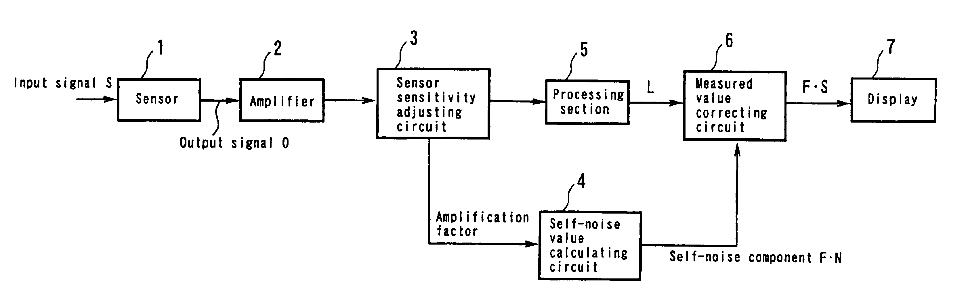
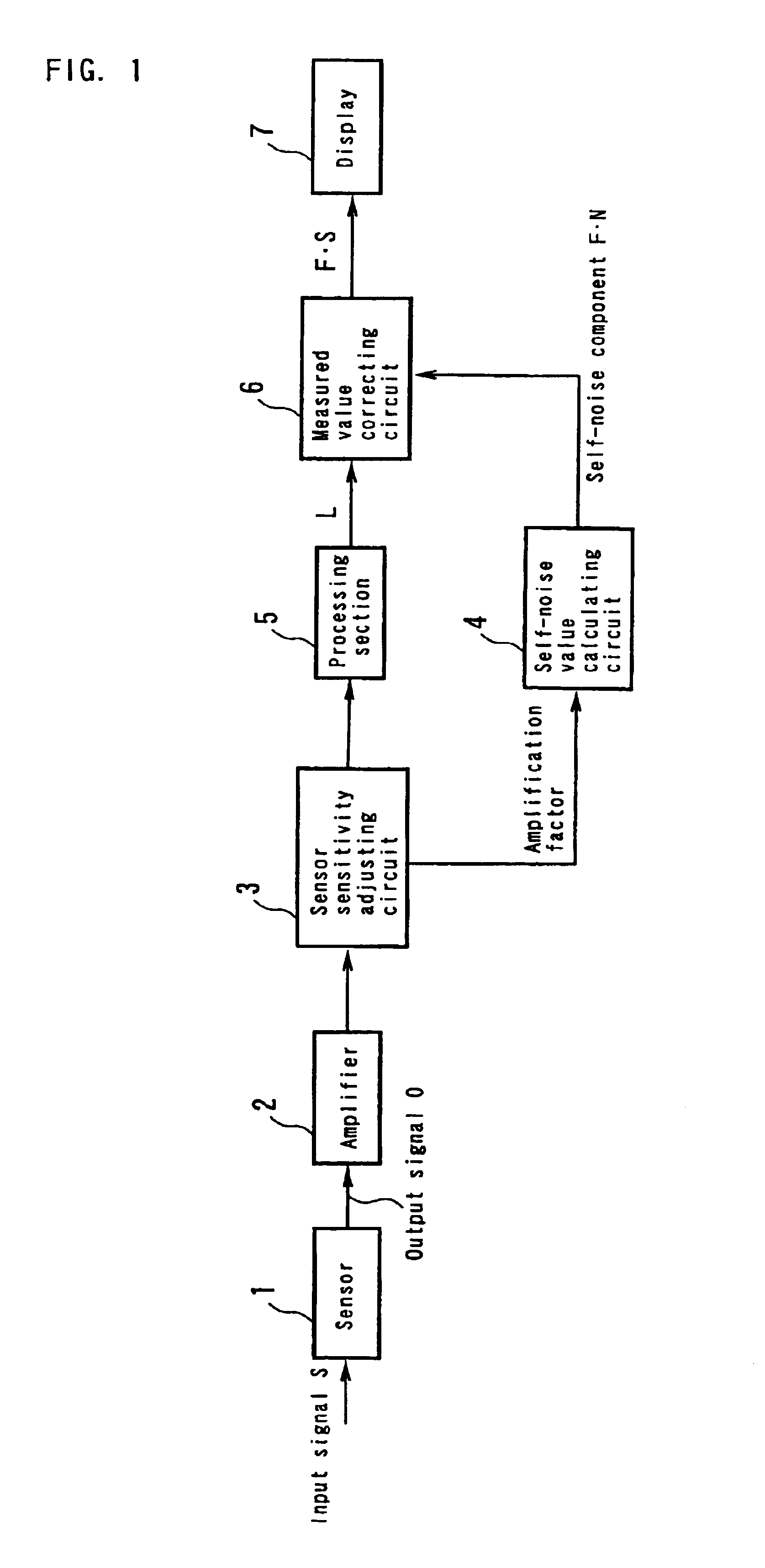
[0072]The measuring equipment provided with the automatic adjusting apparatus according to the present invention comprises a sensor 1, an amplifier 2, a sensor sensitivity adjusting circuit 3, a self-noise value calculating circuit 4, a processing section 5, a measured value correcting circuit 6, and a display 7 as shown in FIG. 1.

[0073]A signal S inputted to the sensor 1 is subjected to an arithmetic process through the amplifier 2, the sensor sensitivity adjusting circuit 3, and the processing section 5. A measured value L as an output signal from the processing section 5 can be expressed as Equation (1).

L=F·(S2+N2)1 / 2  (1)

[0074]In this equation, reference character N denotes self-noise composed of self-noise NM from the sensor 1 and self-noise NA from the amplifier 2 and sensor sensitivity adjusting circuit 3. Reference character F denotes a factor for processing such as leveling or weighting which is executed to convert the input signal S into the measured value L while the inpu...

second embodiment

[0093]Next, measuring equipment provided with an automatic adjusting apparatus according to the present invention comprises a microphone 11, an input switch 12, an input amplifier 13, an amplifying circuit 14 with an amplification factor a, an attenuating circuit 15 with an attenuation factor b, a first A / D converter 16, a second A / D converter 17, a processing section 18, a display 19, and a D / A converter 20 as shown in FIG. 4.

[0094]The processing section 18 is composed of a digital signal generating circuit 21 that generates a plurality of digital signals as reference signals, a synthesizing circuit 22 that synthesizes output signals from the first A / D converter 16 and second A / D converter 17 with each other, an effective-value calculating circuit 23 that executes an arithmetic process on an output signal from the synthesizing circuit 22 to calculate an effective value, a comparing circuit 24 that calculates the amplitude ratio of a value based on the output signal from the first A...

third embodiment

[0127]Next, measuring equipment provided with an automatic adjusting apparatus according to the present invention comprises a microphone 31, an input switch 32, an amplifier 33, a sensor sensitivity adjusting circuit 34 composed of a variable resistor, an A / D converter 35, a processing section 36, a display 37, and a D / A converter 38 as shown in FIG. 9.

[0128]The processing section 36 is composed of a digital signal generating circuit 41 that generates a digital signal R as an internal calibration signal, an effective-value calculating circuit 42 that executes an arithmetic process on an output signal from the A / D converter 35 to calculate an effective value, a comparing circuit 43 that compares an output value from the effective-value calculating circuit 42, i.e. an effective value calculated by the effective-value calculating circuit 42, with a predetermined calibration value, a factor calculating circuit 44 that calculates an adjustment factor for the internal calibration signal o...


PUM


Abstract

An apparatus that automatically adjusts self-noise and can lower the lower limit value of a measurement range by reducing the effects of self-noise on measured values. This apparatus corrects self-noise when amplifying an output signal from a sensor so as to conform to a sensor sensitivity G, further processing the amplified signal, and then outputting the processed signal as a measured value. This apparatus includes a sensor sensitivity adjusting circuit that adjusts an amplification factor so as to conform to the sensor sensitivity G, a self-noise value calculating circuit 4 that calculates a self-noise component F·N from the amplification factor adjusted by the sensor sensitivity adjusting circuit so as to conform to the sensor sensitivity G, and a measured value correcting circuit that calculates a true measured value F·S from the self-noise component F·N calculated by the self-noise value calculating circuit 4 as well as a measured value L containing the self-noise component F·N.

Description

TECHNICAL FIELD[0001]The present invention relates to a method of automatically regulating self-noise or the like which method is applied to measuring equipment such as an audio measuring instrument or a vibration measuring instrument which is provided with a sensor, as well as an apparatus using this method.BACKGROUND ART[0002]Conventional measuring equipment is known which is configured as shown in FIG. 20. That is, in this equipment, a signal S to be measured is inputted to a sensor 100, and an amplifier 101 then amplifies an output signal from the sensor 100 to a predetermined level. Furthermore, a sensor sensitivity adjusting circuit 102 amplifies an output signal from the amplifier 101 to a desired level compatible with the sensitivity of the sensor 100. Then, a processing section 103 executes processes such as an effective value operation and A / D conversion on an output signal from the sensor sensitivity adjusting circuit 102. Finally, a display 104 displays an output signal ...

Claims


Application Information

Patent Timeline
Patent Type & Authority Patents(United States)
IPC IPC(8): G01D3/032G01D3/028G01D3/00G01D3/02H03M1/10H03M1/18
CPCG01D3/032H03M1/1019H03M1/188
Inventor WAKABAYASHI, TOMOHARUOHYA, MASAHARUKOBAYASHI, KAZUYOSHITAKINAMI, HIROAKITAKEDA, NOBUHIKO
Owner RION COMPANY
Why Eureka
Try Eureka