Prefabricated shearwall having improved structural characteristics

a prefabricated and structural technology, applied in the direction of structural elements, building components, shock proofing, etc., to achieve the effect of variable stiffness, exceptional structural performance, and desired ductility

Inactive Publication Date: 2005-08-23
SHEAR FORCE WALL SYST
View PDF25 Cites 42 Cited by
  • Summary
  • Abstract
  • Description
  • Claims
  • Application Information

AI Technical Summary

Benefits of technology

[0009]The present invention has incorporated a number of features into a prefabricated shearwall that provide exceptional structural performance compared to site-built or even prefabricated shearwalls of the prior art. One favorable aspect of the present invention is that it provides a shearwall with variable stiffness along the height of the wall. In particular, the prefabricated shearwall of the present invention possesses the desired ductility of a conventionally framed shearwall while it simultaneou

Problems solved by technology

Furthermore, the shearwall is sheathed with plywood or OSB that

Method used


Image

  • Prefabricated shearwall having improved structural characteristics
  • Prefabricated shearwall having improved structural characteristics
  • Prefabricated shearwall having improved structural characteristics

Examples


Embodiment Construction

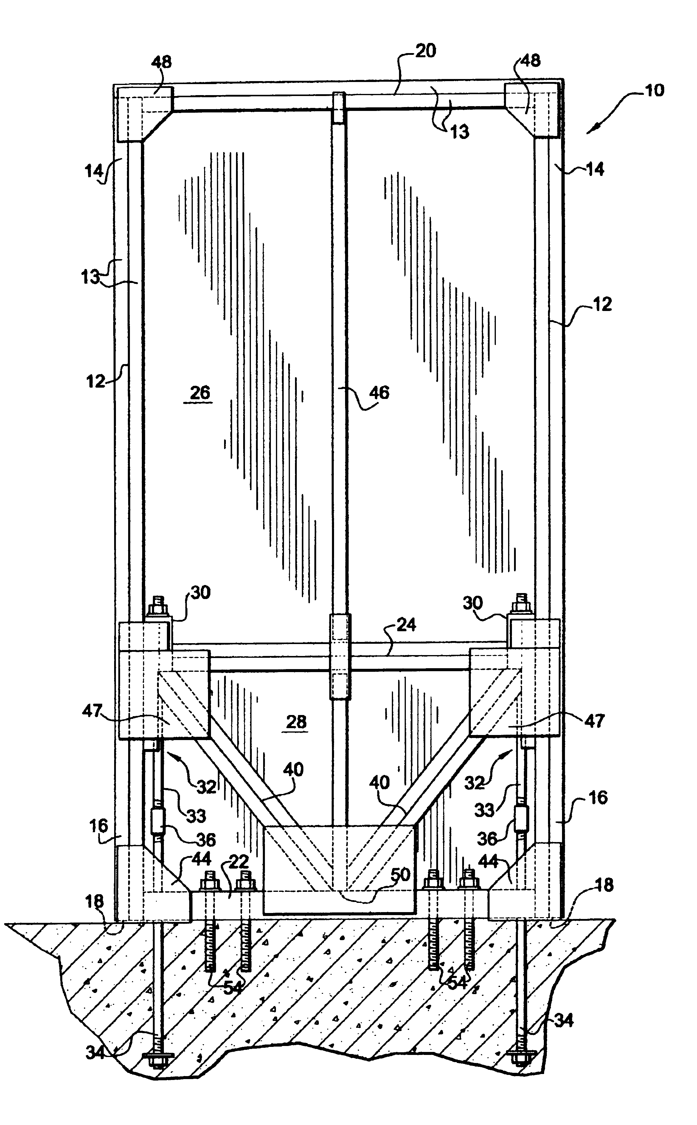
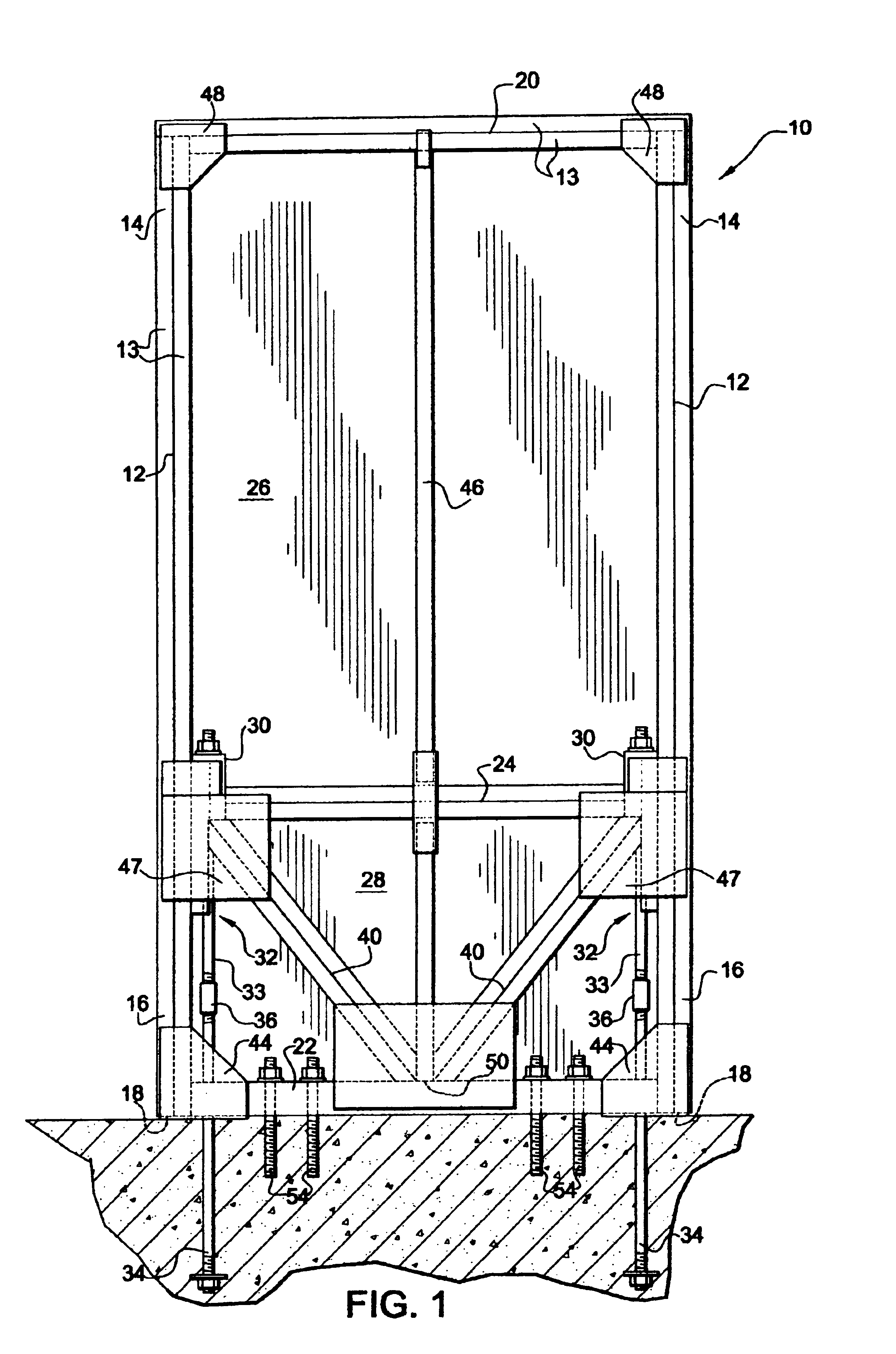
[0020]A front view of a prefabricated shearwall according to the present invention is shown in FIG. 1. The prefabricated shearwall 10 has spaced apart supporting substantially vertical members 12 that may each comprise, for example, one or more boards 13 of dimensional lumber. Individual boards 13 forming each vertical member 12 may be positioned adjacent one another and secured together in any conventional manner using, for example, glue, nails, screws, bolts, and the like, or may be unsecured. In general, supporting vertical members can include boards, posts, or other elongated structures used to support a shearwall secured to a foundation in a substantially vertical alignment, where the plane of the shearwall is substantially vertical or perpendicular to the foundation. The perpendicular plane of the shearwall may contain a rectangularly shaped frame structure having vertical members, such as the shearwall depicted in FIG. 1. Alternatively, the perpendicular plane of the shearwal...


PUM


Abstract

A novel prefabricated shearwall is disclosed with improved structural characteristics in terms of its ability to 1) transfer lateral loads to the foundation, 2) resist bending moments normally arising in conventional shearwalls between hold-down hardware and end posts or vertical framing members, 3) effectively diffuse stresses known to result in nail fatigue, and 4) reduce slippage between the bottom of the end posts and base in response to cyclic loadings. These superior properties result partly from its geometry in lower, or shear force transfer region, accompanied by thrust block/anchor rod assemblies to provide stiffness and strength over the lower portion of the end posts. Furthermore, specialized wrap-around connector plates that cover a portion of the bottom surface of these end posts also contribute to the enhanced prefabricated shearwall design.

Description

CROSS-REFERENCE TO RELATED APPLICATION[0001]This application claims priority from Provisional Application Ser. No. 60 / 299,471 filed Jun. 21, 2001, the contents of which are hereby incorporated by reference.FIELD OF THE INVENTION[0002]The present invention relates to a novel shearwall exhibiting superior structural characteristics. More specifically, the present invention relates to a shearwall with an upper region having ductile properties to dissipate seismic energy and a lower region having improved strength and stiffness properties to resist lateral loads.BACKGROUND OF THE INVENTION[0003]A shearwall is a common structural component of buildings, especially wood frame buildings, that is specifically designed to resist lateral forces due to wind and seismic loads. Typically, shearwalls are constructed on site using plywood or oriented strand board (OSB) sheathing nailed to dimensional lumber studs (e.g., “two by” boards) and plates, together with special hardware connecting the she...

Claims


Application Information

Patent Timeline
IPC IPC(8): E02D27/32E04B1/26E04H9/02E04B1/00E04B2/56E04C5/00E04G23/04E04H9/14
CPCE02D27/32E04B1/26E04H9/02E04B2001/2684E04H9/0237
Inventor TRARUP, GLENN M.LEUNG, THOMAS V.SHAHNAZARIAN, GEORGE
Owner SHEAR FORCE WALL SYST
Why Eureka
Try Eureka