Vehicle air conditioner

a technology for air conditioners and vehicles, applied in the field of vehicles, can solve problems such as passengers' unpleasant noise, and achieve the effect of controlling the rotation speed of the compressor

Active Publication Date: 2005-08-23
DENSO CORP
View PDF4 Cites 15 Cited by
  • Summary
  • Abstract
  • Description
  • Claims
  • Application Information

AI Technical Summary

Benefits of technology

[0012]Accordingly, the rotation speed of the compressor can be controlled by stopping the compressor for the predetermined period of time. It is not necessary to detect a rotational position of the compressor. Therefore, when the target rotation speed is higher than the upper l...

Problems solved by technology

As a result, it is less likely that noise caused by the com...

Method used


Image

  • Vehicle air conditioner
  • Vehicle air conditioner
  • Vehicle air conditioner

Examples


first embodiment

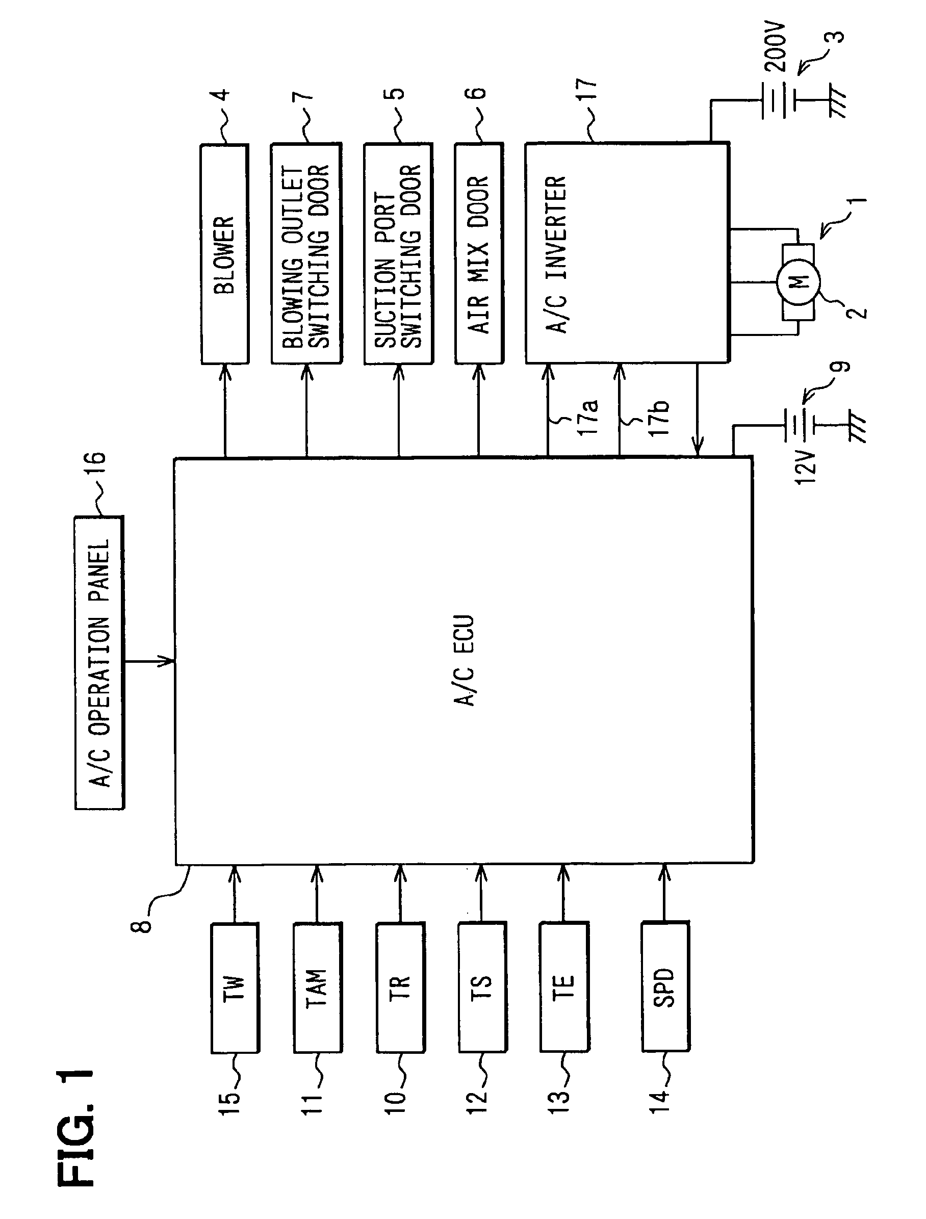
[0021]An air conditioner of the first embodiment is mounted on an electric vehicle. A control system of the air conditioner is shown in FIG. 1. The air conditioner includes a refrigerant cycle having a compressor 1. The compressor1 is an electric compressor that is driven by an electric motor 2 mounted on the vehicle. The electric motor 2 is driven by receiving electric power from a battery 3 mounted on the vehicle.

[0022]The refrigerant cycle further includes, a condenser, a receiver, an expansion valve, and an evaporator. In the refrigerant cycle, a high-temperature, high-pressure refrigerant compressed by the electric compressor 1 is condensed in the condenser. The condensed liquid refrigerant is separated into gas refrigerant and liquid refrigerant in the receiver. Then, the liquid refrigerant from the receiver is decompressed and expanded through the expansion valve. Further, the low-temperature, low-pressure refrigerant expanded in the expansion valve is evaporated in the evapo...

second embodiment

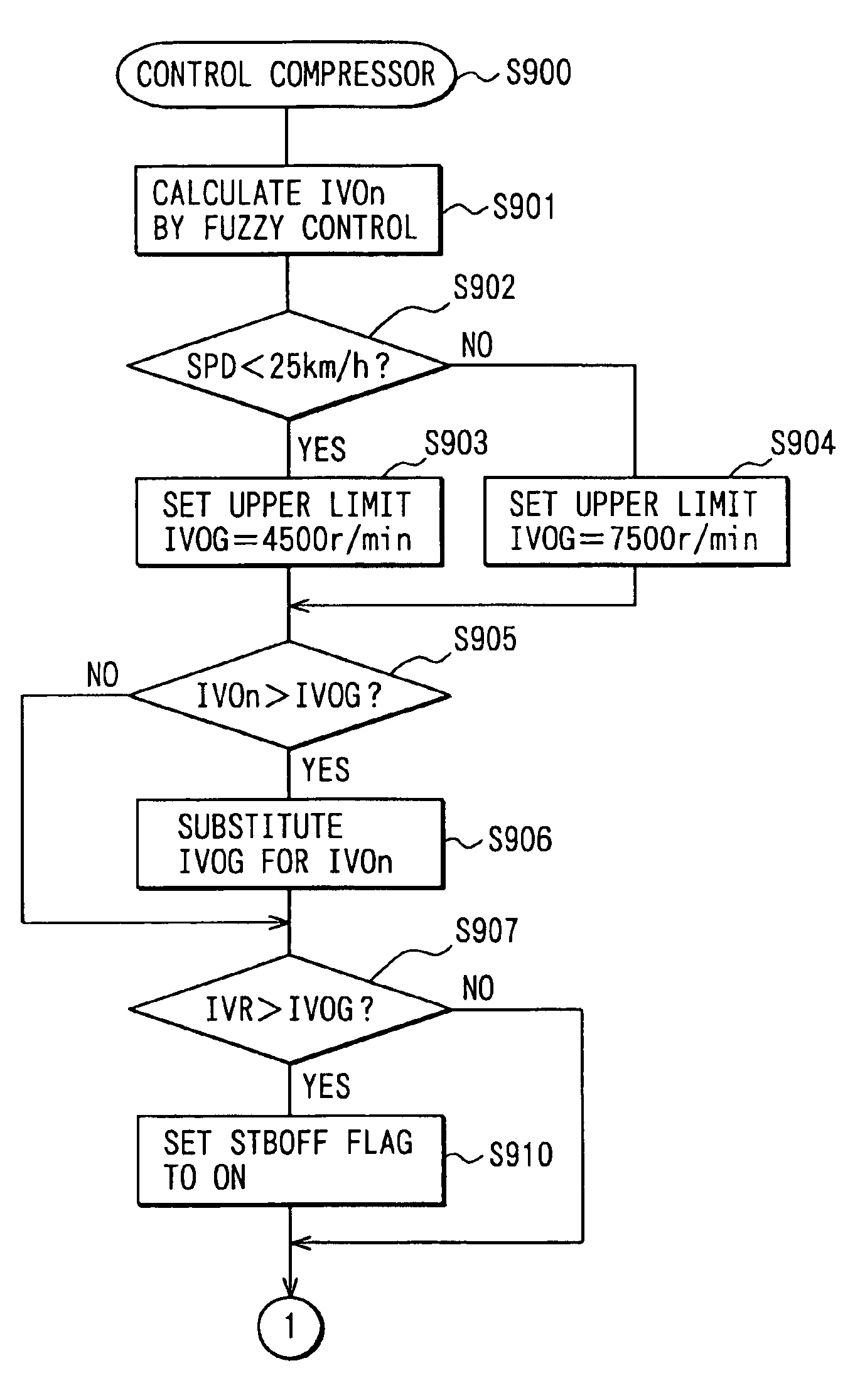
[0046]FIG. 6 shows the present invention. To immediately decrease the rotation speed of the compressor 1 to the low level, as shown in FIG. 6, the value of the rotation speed indicating signal, which is outputted to the inverter 17 from the air conditioner ECU 8, is set to zero for the predetermined period of time T while maintaining the inverter starting signal STB on.

[0047]Similar to the first embodiment shown in FIG. 5, the rotation speed of the compressor 1 can be controlled by setting the rotation speed of the rotation speed indicating signal to zero for the predetermined period of time T. Therefore, it is necessary to detect the rotational position of the compressor 1. When the target rotation speed IVOn is higher than the upper limit IVOG and the vehicle noise level is reduced from the level that is equal to or higher than the predetermined level (Spd≧25 km / h) to the level that is lower than the predetermined level (Spd1 can be immediately decreased. Accordingly, it is less l...


PUM


Abstract

In an air conditioner for a vehicle, when a target rotation speed of an electric compressor calculated by a target rotation speed calculating means is higher than an upper limit set by an upper limit setting means and a noise level is reduced from a level equal to or higher than a predetermined noise level to a level lower than the predetermined noise level, an inverter controls the compressor to stop for a predetermined period of time and subsequently increase rotation speed to the upper limit. Since the compressor is stopped for the predetermined period of time, the rotation speed of the compressor is controlled without detecting a rotational position of the compressor. Therefore, when the target rotation speed is higher than the upper limit and the noise level is decreased lower than the predetermined noise level, an actual rotation speed of the compressor is immediately decreased.

Description

CROSS-REFERENCE TO RELATED APPLICATION[0001]This application is based on Japanese Patent Application No. 2003-33575 filed on Feb. 12, 2003, the disclosure of which is incorporated herein by reference.FIELD OF THE INVENTION[0002]The present invention relates to a vehicle air conditioner that controls the rotation speed of an electric compressor while performing air-conditioning operation of a compartment.BACKGROUND OF THE INVENTION[0003]In an air conditioner in which an air conditioning operation is performed by rotating an electric compressor, noise caused by the rotation of the compressor is likely to result in unpleasant noise for passengers, depending on a vehicle noise level.[0004]For example, if the speed of a vehicle is equal to or higher than a predetermined speed, the vehicle noise level will be high because of road noises and the like. Therefore, the noise caused by the rotation of the compressor will less likely to affect the ear unpleasantly. On the other hand, if the veh...

Claims


Application Information

Patent Timeline
IPC IPC(8): B60H1/32B60H1/00
CPCB60H1/3205B60H2001/006B60H2001/3266B60H2001/327B60H2001/3272F25B2500/12F25B2600/021F25B2600/025
Inventor OOMURA, MITSUYOHOMAN, TOSHINOBUKISHITA, HIROSHI
Owner DENSO CORP
Why Eureka
Try Eureka