Lock for a sliding door or gate

a technology for sliding doors and gates, applied in the direction of keyhole guards, mechanical control devices, restricting/preventing/returning movement of parts, etc., can solve the problems of large rectangular holes to be made for bolts in the profile, damage to spring steel bands, and large forces in bolts

Inactive Publication Date: 2005-08-23
TALPE JOSEPH
View PDF21 Cites 14 Cited by
  • Summary
  • Abstract
  • Description
  • Claims
  • Application Information

AI Technical Summary

Benefits of technology

[0011]An object of the present invention is therefore to provide a new type of lock for a sliding door or gate which enables to close the door or gate without having to operate the handle and this without requiring spring steel bands in the reception element to allow the head of the latch bolt to pass or a shroud member around the latch bolt to keep it in its unlocking position once the door or gate has been opened.
[0013]In order to lock the door or gate, the bolt has not to be lifted or moved transversally to its longitudinal direction but can simply be rotated about its longitudinal axis. An advantage of such a lock is that when mounting the lock against one side of a profile of the door or gate so that the bolt extends through this profile only a relatively small cylindrical hole must be provided in this profile for receiving the shaft portion of the bolt. It is clear that such a hole can easily be drilled in the profile. A further advantage of the lock according to the invention is that, when closing the door or gate, the latch bolt is automatically rotated to its unlocking position by mechanical contact between the lateral surface of the lock wing and the reception element, in particular with the slot therein. In this way, the lateral edges of the slot in the reception element do not have to be elastic to allow the head of the latch bolt to pass or no shroud member has to be provided around the latch bolt to keep it in its unlocked state when having opened the door or gate. The latch bolt structure of the lock according to the invention can therefore be kept quite compact and a strong connection with the reception element can be obtained which can resist the high rebound forces arising when slamming a sliding door or gate.
[0015]In this embodiment, after having removed the first part with the head portion, the latch bolt can easily be applied through a small hole in a profile and the first part can subsequently be mounted again onto the free extremity of the second part which projects out of the profile. The first part is preferably screwed onto the second part in order to be able to resist the high traction forces which may occur as a result of the rebound of the sliding door or gate against the door post when closing it.

Problems solved by technology

Indeed, when closing the sliding door or gate, the rebound of the door or gate against the opposite door post to which the bolt reception element is fixed may cause considerably large forces in the bolt.
A drawback of such a hook-shaped latch bolt is that when mounting the lock against a profile of the door or the gate so that the bolt has to extend entirely through this profile, a quite large rectangular hole has to be made for the bolt in the profile.
A drawback of such an arrangement is that the spring steel bands can become damaged by the large rebound forces arising when closing a sliding door or gate.
A drawback of such a shroud member is that it complicates the lock and that it requires a relative large construction around the latch bolt.
Consequently, the lock disclosed in GB-B-1 111 513 is not suited for being mounted against an upright of a door or gate so that the latch bolt extends through this upright since a relatively large hole is needed to pass the latch bolt and the surrounding construction with the shroud member through the upright.

Method used


Image

  • Lock for a sliding door or gate
  • Lock for a sliding door or gate
  • Lock for a sliding door or gate

Examples


Embodiment Construction

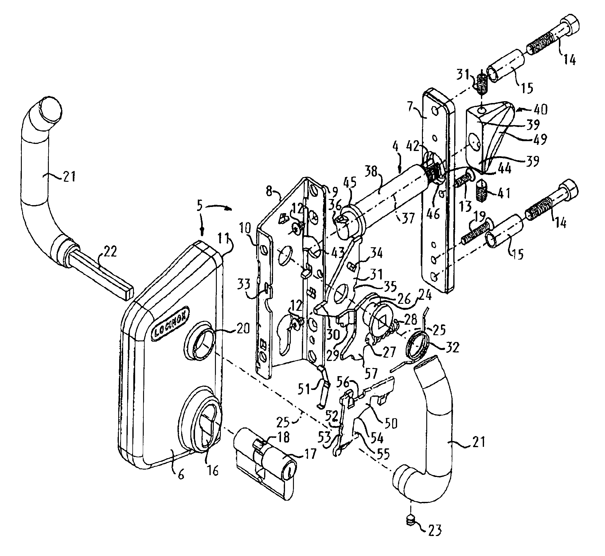
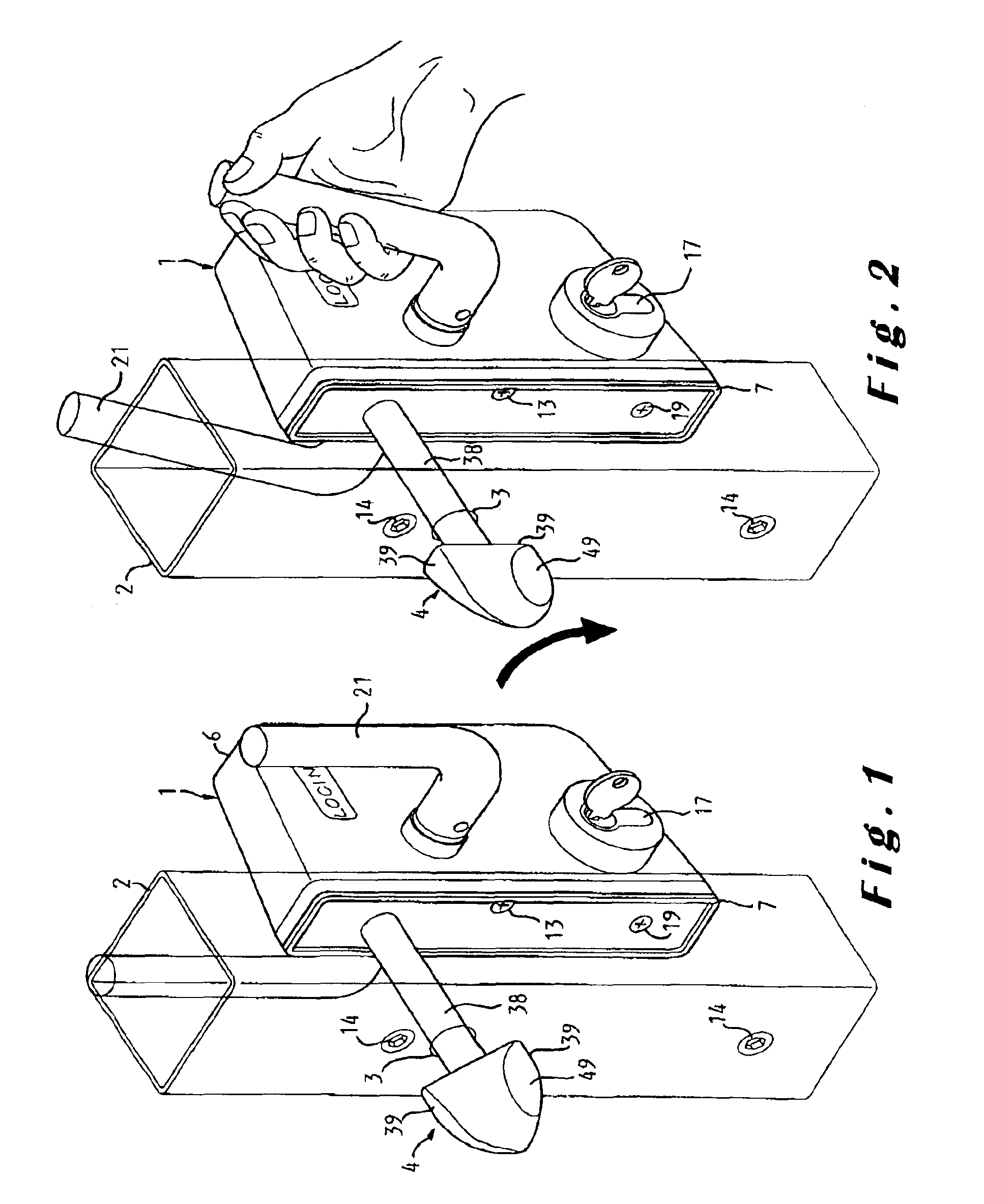
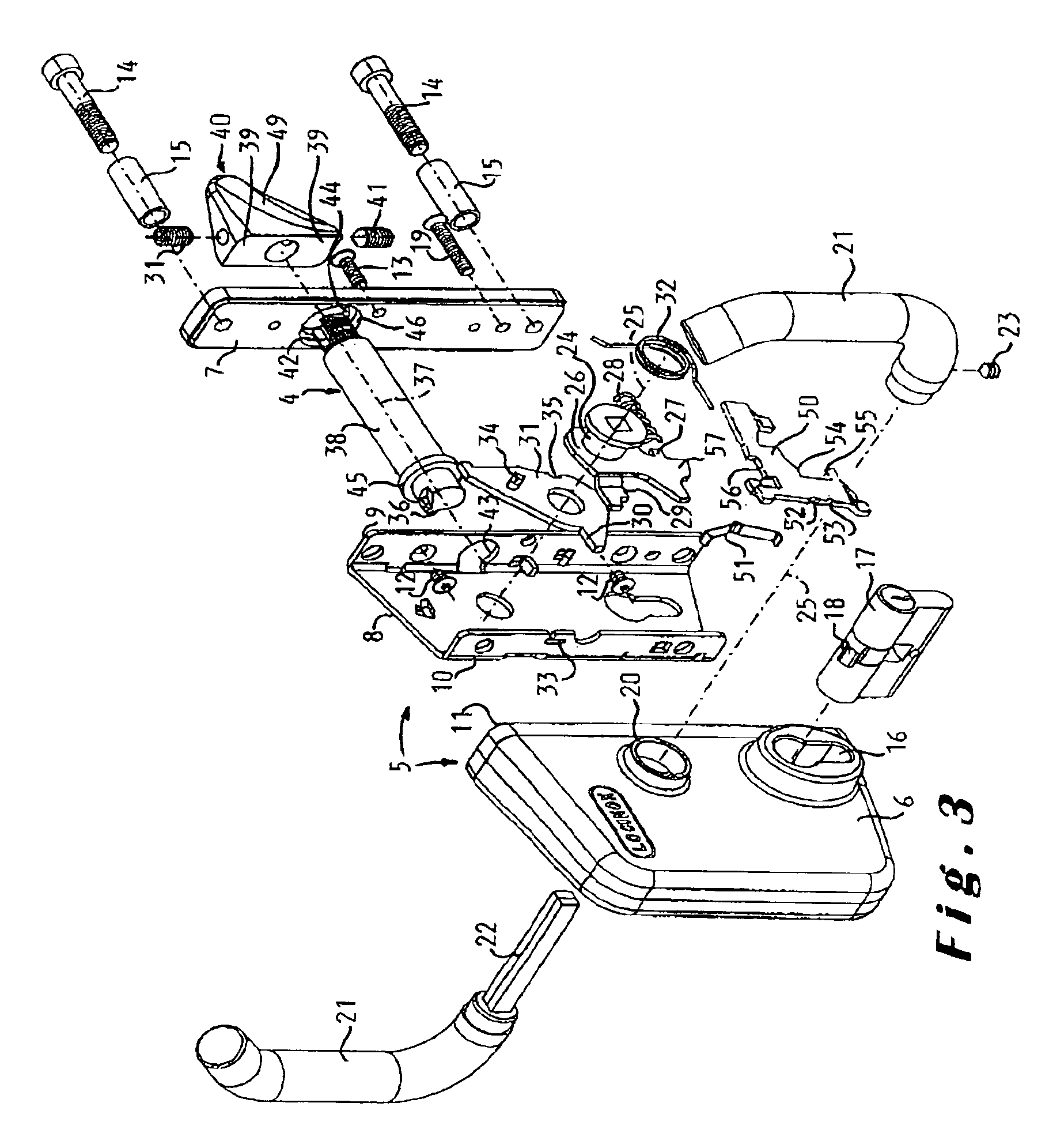
[0033]The lock 1 shown in the drawings is a lock provided to be mounted against a profile 2, in particular a tubular profile, of a sliding door or gate. In the present specification, the term door is intended to embrace doors, gates and any other similar closure structure. The profile 2 is provided with a cylindrical hole 3 so that the latch bolt 4 of the lock 1 can project there through. This latch bolt 4 can be rotated by means of the handles from the locking position illustrated in FIG. 1 to the unlocking position illustrated in FIG. 2.

[0034]The illustrated lock 1 comprises a frame 5 composed of a cover box 6, a front cover plate 7 for closing the box 6 and a base plate 8 arranged within the closed box 6. The base plate 8 has on its front side an upstanding edge 9 and on its back side a further upstanding edge 10. The cover box 6 has such dimensions that the base plate 8 can be slid completely therein, more particularly through the substantially rectangular front opening 11 of th...


PUM


Abstract

The lock comprises a frame (5), at least one bolt (4), in particular a latch bolt which projects in a predetermined direction out of the frame, a bolt operating mechanism (26, 31, 32) and means (20, 24) for mounting at least one hand operated actuating element (21) for said bolt operating mechanism on the frame so that this actuating element can rotate on the frame according to a rotation axis (25) extending in particular perpendicular to said predetermined direction. The bolt (4) comprises a shaft portion (38) and at least one laterally projecting lock wing (39) and is rotatably mounted on the frame according to a further rotation axis (37) extending in said predetermined direction, the bolt operating mechanism being arranged to rotate the bolt (4) between a first angular orientation, wherein the lock wing (39) of the bolt is in the locking position, and a second angular orientation, wherein the lock wing of the bolt is in the unlocking position.

Description

RELATED APPLICATION[0001]This patent application claims priority of European Patent Application No. 02447021.3, filed Feb. 11, 2002.[0002]1. Field of the Invention[0003]The present invention relates to a lock for a sliding door or gate comprising a frame; a latch bolt comprising a shaft portion and at least one laterally projecting wing on the shaft portion, the shaft portion projecting in a predetermined direction out of the frame and being rotatably mounted on the frame according to a rotation axis extending in said predetermined direction; and a latch bolt operating mechanism arranged to rotate the latch bolt from a first angular orientation, wherein the lock wing of the bolt is in a locking position, to a second angular orientation, wherein the lock wing of the bolt is in an unlocking position and vice versa, the latch bolt operating mechanism comprising a resilient element arranged to urge the latch bolt from its second to its first angular orientation.[0004]2. Background[0005]...

Claims


Application Information

Patent Timeline
Patent Type & Authority Patents(United States)
IPC IPC(8): E05B65/08E05C3/00E05B13/00E05B15/00E05B15/02
CPCE05B65/0841E05C3/006E05B13/004E05B15/0205Y10T292/1046Y10T292/68Y10T70/577Y10T292/1056
Inventor TALPE, JOSEPH
Owner TALPE JOSEPH
Why Eureka
Try Eureka