Post singulation die separation apparatus and method for bulk feeding operation

Active Publication Date: 2005-08-23
NAT SEMICON CORP
View PDF6 Cites 20 Cited by
  • Summary
  • Abstract
  • Description
  • Claims
  • Application Information

AI Technical Summary

Benefits of technology

[0011]The present invention is directed to a post singulation, die separation assembly configured for bulk separation of a plurality of dice in a singulated wafer from the adhesive backing of wafer saw tape. The die separation assembly includes a support base defining a support surface having a first portion and an opposite second portion thereof. The second portion include a down-ramped portion skewed downwardly at a first acute angle from the support surface. The separation assembly further includes a feed tray having a collection end positioned adjacent the base second portion such that an elongated, substantially thin gap is formed between the tray collection end and at least a portion of the base second portion. A flexible platform is movably supported atop the base support surface for movement

Problems solved by technology

An exemplary flip chip die may be about 35 mils square, which limits the applicable handling techniques.
To dislodge the die from the adhesive of the wafer saw tape 20, however, the vacuum tube approach alone is usually insufficient.
While these current device transfer machines adequately perform their respective functions, they are problematic for a number of

Method used


Image

  • Post singulation die separation apparatus and method for bulk feeding operation
  • Post singulation die separation apparatus and method for bulk feeding operation
  • Post singulation die separation apparatus and method for bulk feeding operation

Examples


Example

[0026]While the present invention will be described with reference to a few specific embodiments, the description is illustrative of the invention and is not to be construed as limiting the invention. Various modifications to the present invention can be made to the preferred embodiments by those skilled in the art without departing from the true spirit and scope of the invention as defined by the appended claims. It will be noted here that for a better understanding, like components are designated by like reference numerals throughout the various figures.

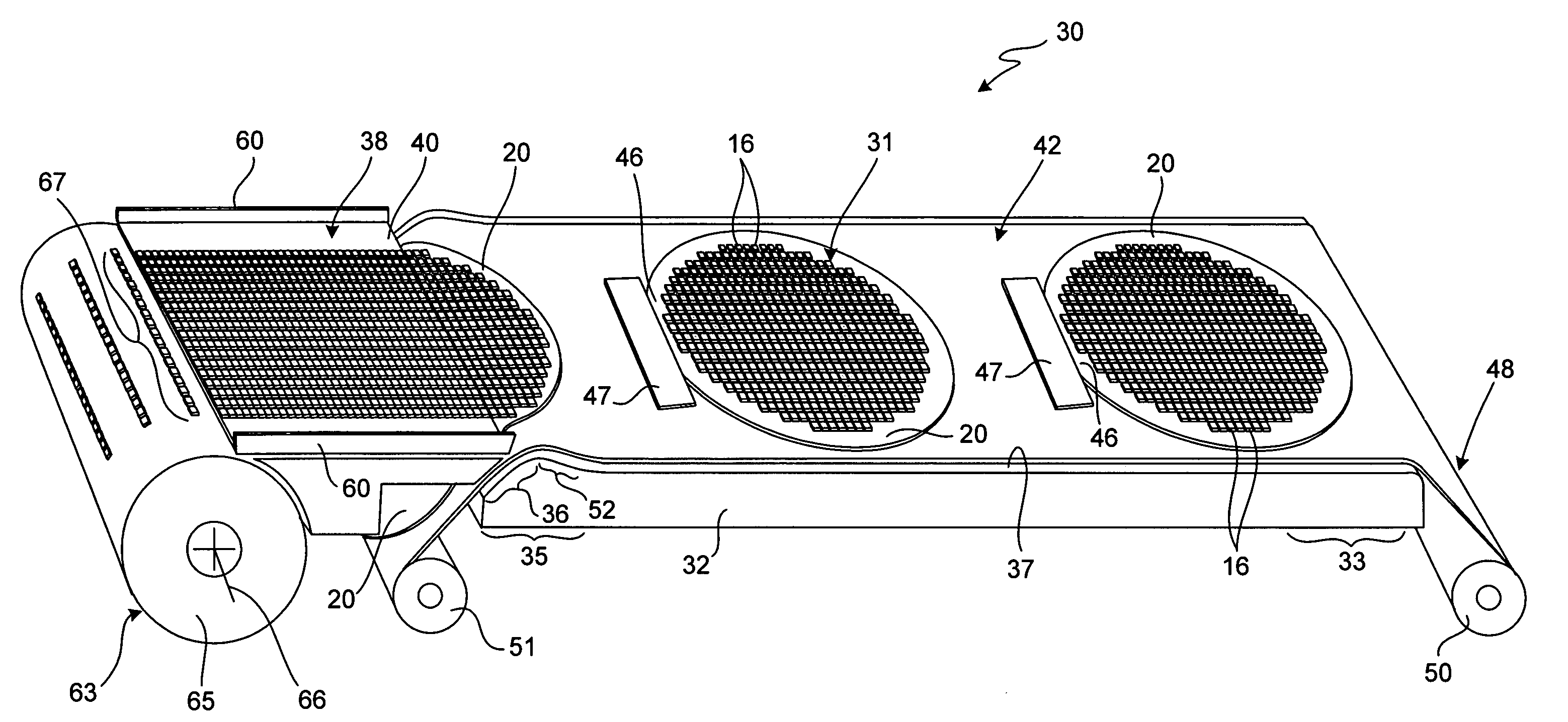
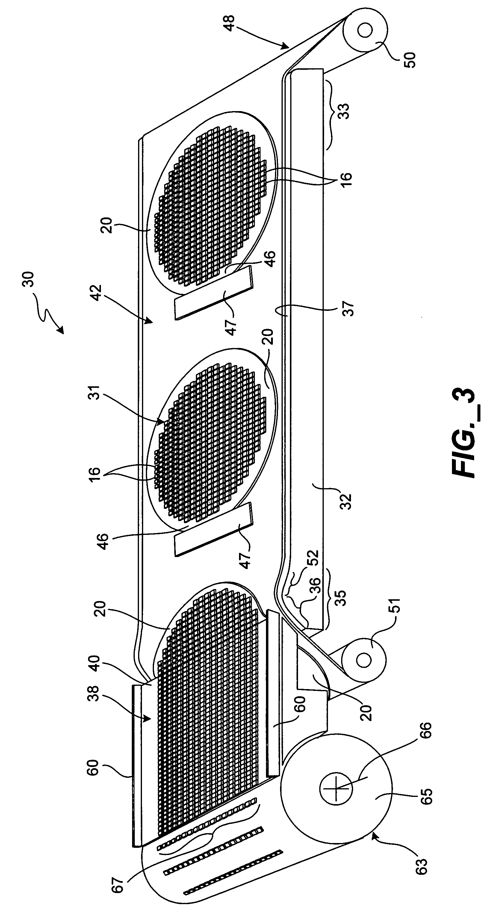
[0027]Attention is now directed to FIGS. 3 and 4, where a post singulation, die separation assembly, generally designated 30, is illustrated for bulk separation of a plurality of dice 16 of a post singulated wafer assembly 31 from the adhesive wafer saw tape 20. The die separation assembly 30 includes an elongated support base 32 having a support surface extending from a first portion 33, on one side of the base, to a second portio...


PUM

PropertyMeasurementUnit
Angleaaaaaaaaaa
Angleaaaaaaaaaa
Angleaaaaaaaaaa

Abstract

A post singulation, die separation assembly for bulk separation of a plurality of dice in a singulated wafer from the adhesive backing of wafer saw tape. The die separation assembly includes a support base having a support surface, a first portion and an opposite second portion thereof. The second portion includes a down-ramped portion thereof skewed downwardly at a first acute angle from the support surface. A feed tray includes a collection end positioned adjacent the base second portion such that an elongated, substantially thin gap is formed between the tray collection end and at least a portion of the base second portion. A flexible platform is movably supported atop the base support surface for movement from the first portion to the second portion thereof. At the second portion, the platform passes downward through the gap formed between the tray collection end and the at least a portion of the base second portion. The platform defines an upward facing surface upon each die of the singulated wafer is adhered thereto, via the saw tape, in a forward aligned manner. Upon movement of the flexible platform down the down-ramped portion of the support base, a portion of the wafer saw tape thereat is peeled away from the respective die. The tape is the separated from the dice, releasing the respective dice onto the collection end of the feed tray in a manner substantially maintaining their forward alignment orientation of thereof.

Description

BACKGROUND OF THE INVENTION[0001]1. Field of the Invention[0002]The present invention relates generally to post die singulation of wafers, and more particularly, relates to separation of dice from wafer saw tape while substantially retaining the orientation die during separation.[0003]2. Description of the Related Art[0004]Semiconductor Integrated Circuits (ICs) are typically fabricated in wafer form on wafer saw tape. After fabrication, using precision cutting techniques, individual die are cut or singulated from the wafer without cutting through the saw tape. In the past, where the precise orientation of the die was necessary, a tape and reel assembly was typically applied to transport the chips to the individual processing stations. The tape and reel assembly includes a tape with a plurality of transport cavities spaced at regular intervals. Once a chip has been placed inside a transport cavity, the cavity is sealed with an adhesive tape so the chip can be safely transported from...

Claims


Application Information

Patent Timeline
IPC IPC(8): H01L21/00
CPCH01L21/67132H01L2221/68322Y10T156/1179Y10T156/19Y10S156/941
Inventor KELKAR, NIKHILPHAM, KENBAYAN, JAIME A.HAN, CHEOL HYUN
Owner NAT SEMICON CORP
Why Eureka
Try Eureka