
Capacity indicating device and method thereof

a technology of capacity indicating device and battery, which is applied in the direction of electric devices, hybrid vehicles, instruments, etc., can solve the problems of inability to obtain the effects of the previously described absolute capacity indicator, increase in the internal resistance of the battery, and constant time per segment, so as to reduce the effect of capacity change, accurate estimation of cruising distance, and constant possible traveling distan

Inactive Publication Date: 2005-08-23
NISSAN MOTOR CO LTD
View PDF12 Cites 44 Cited by
  • Summary
  • Abstract
  • Description
  • Claims
  • Application Information

AI Technical Summary

Benefits of technology

The present invention provides a capacity indicating device and method for a vehicle battery that can reduce the effect of battery degradation on the capacity indication, indicate a fully charged state accurately, and prevent the user from experiencing a feeling of something being wrong with the capacity indication. The device includes a first indicator for a first portion of the battery capacity, a second indicator for a second portion of the battery capacity, and an indication control unit that activates the first indicator based on the present battery capacity and corrects the second prescribed capacity in response to the degree of degradation of the battery to maintain the first prescribed energy capacity after the degree of degradation of the battery.

Problems solved by technology

It has been discovered that the internal resistance of a battery increases as the battery degrades over time.
This creates a problem in that the user feels something is wrong with the capacity indication because the indicating device does not indicate a fully charged state even though full recharging was performed.
In this kind of relative capacity indicator, the possible traveling time per segment is not constant and the effects of the previously described absolute capacity indicator cannot be obtained.

Method used


Image

  • Capacity indicating device and method thereof
  • Capacity indicating device and method thereof
  • Capacity indicating device and method thereof

Examples


Embodiment Construction

[0020]Selected embodiments of the present invention will now be explained with reference to the drawings. It will be apparent to those skilled in the art from this disclosure that the following descriptions of the embodiments of the present invention are provided for illustration only and not for the purpose of limiting the invention as defined by the appended claims and their equivalents.

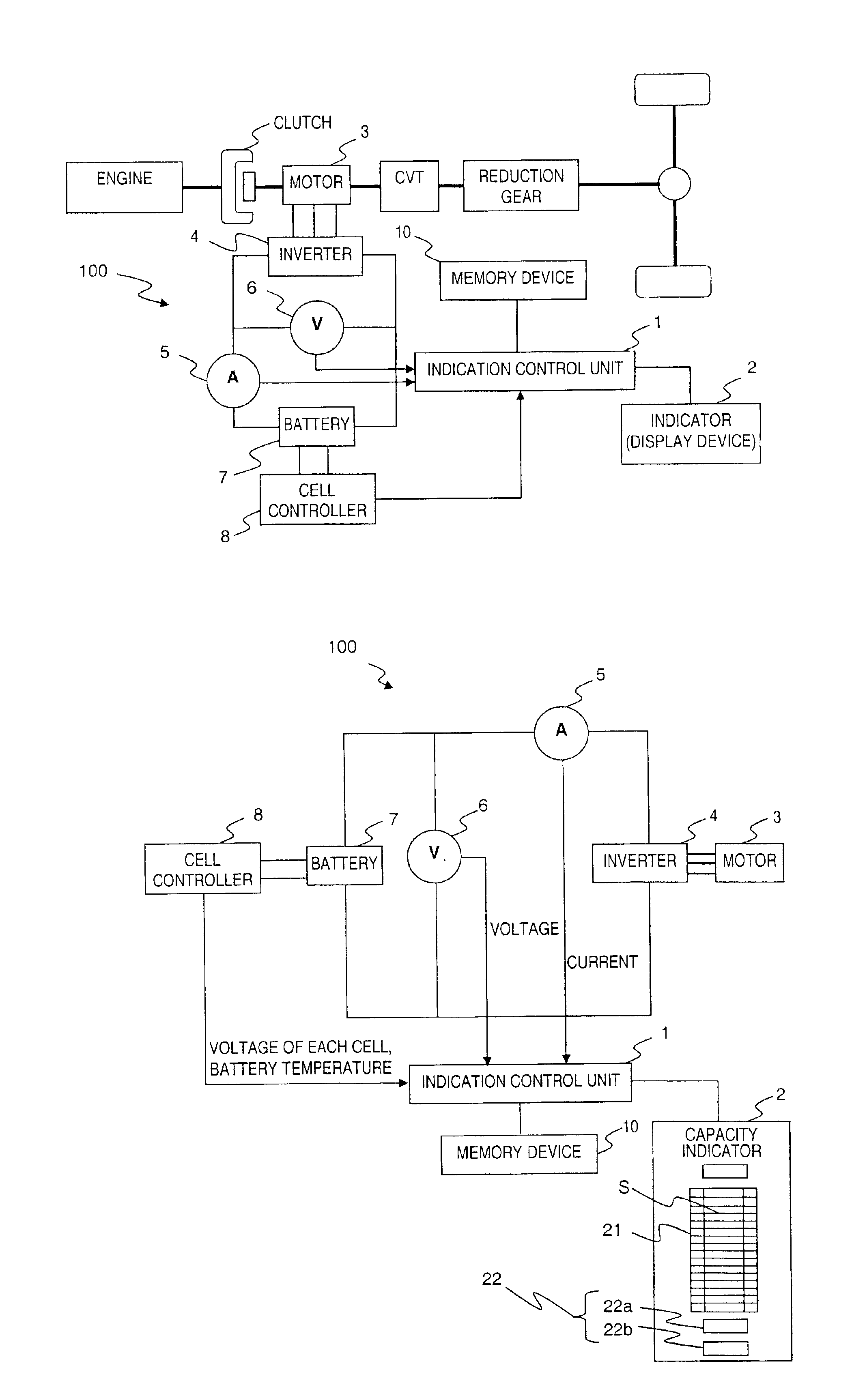
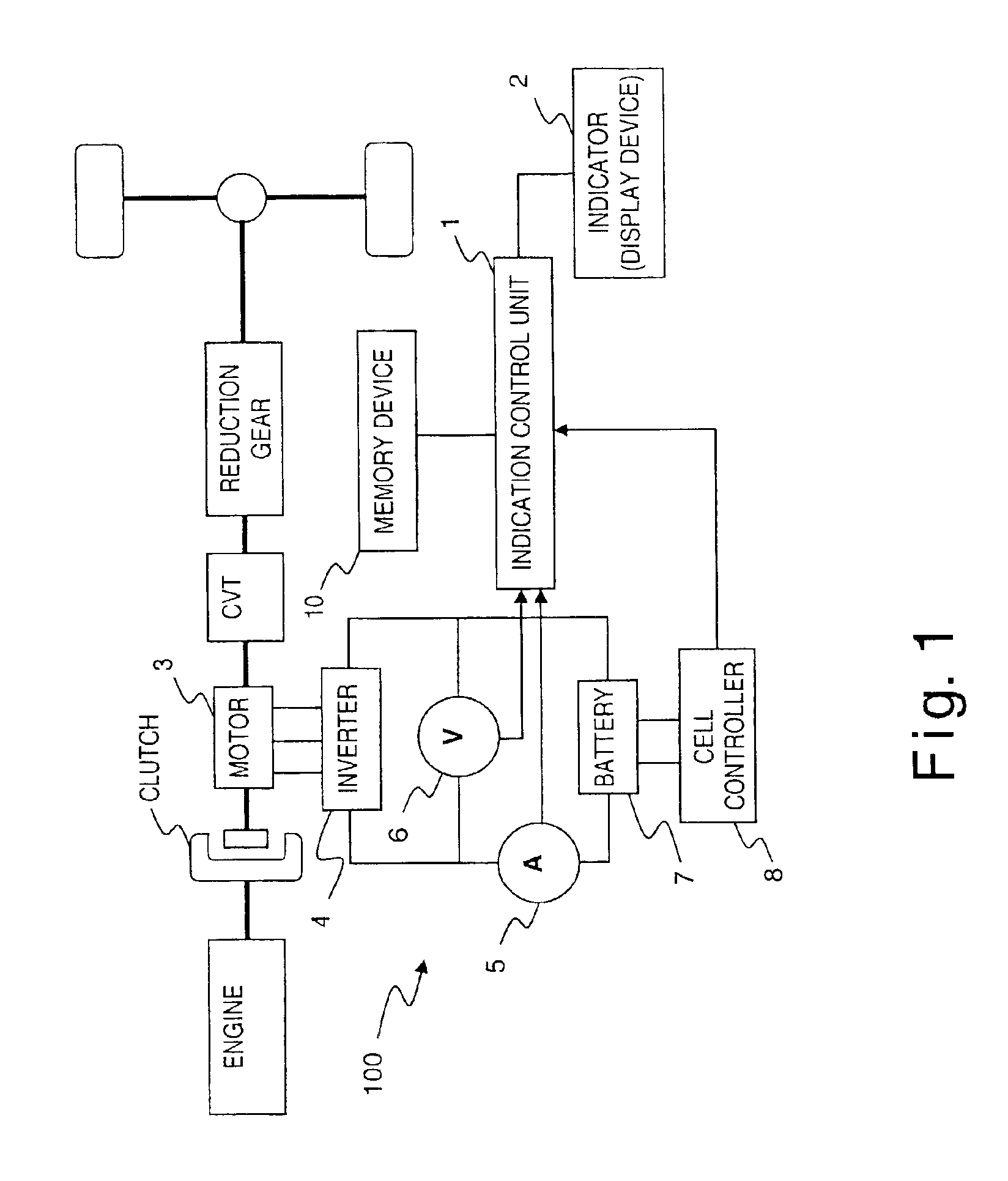
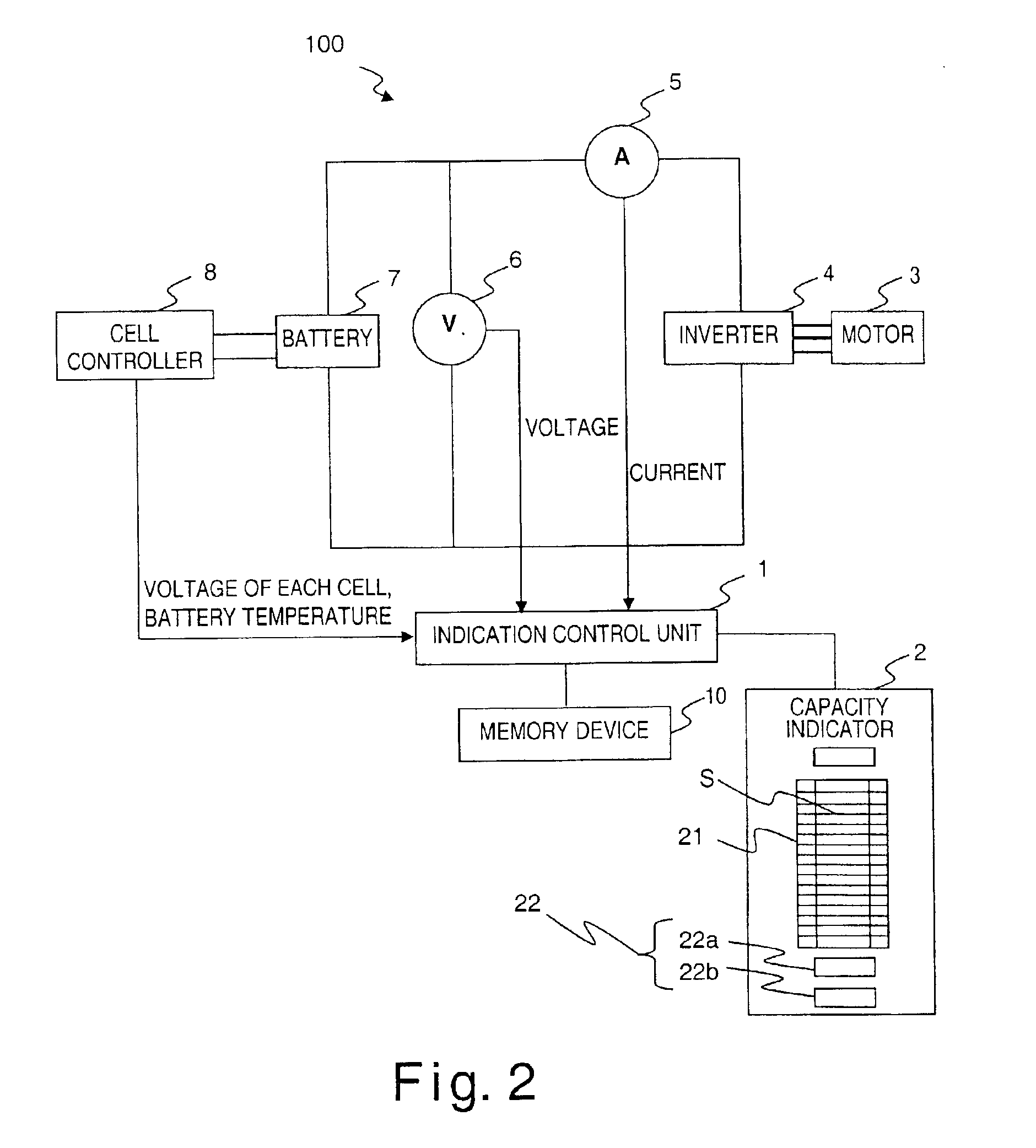
[0021]Referring initially to FIG. 1, a simplified schematic view of a hybrid vehicle is illustrated that is equipped with a battery capacity indicating device 100 having an indication arrangement in accordance with a first embodiment of the present invention. Referring to FIG. 2, the capacity indicating device 100 is schematically illustrated by itself. The capacity indicating device 100 basically comprises an indication control unit (battery controller) 1, a capacity indicator (display) 2, a motor 3, an inverter 4, a current detecting device (current sensor) 5, a voltage detecting device (voltage ...


PUM

PropertyMeasurementUnit
temperatureaaaaaaaaaa
traveling distanceaaaaaaaaaa
energy capacityaaaaaaaaaa

Abstract

A capacity indicating device is configured to indicate a fully charged state when full recharging has been conducted even if the battery is degraded; hold the possible traveling distance per segment roughly constant; and make it easy to estimate the possible cruising distance. The capacity indicating device has an indication control unit that: (1) allocates a prescribed portion of the battery capacity of a vehicle to a capacity adjustment region that serves to adjust the battery capacity as it decreases due to degradation of the battery; (2) calculates the degradation degree of the battery based on the detected voltage value and current value; (3) corrects the capacity adjustment region a based on the calculated degradation degree; and (4) indicates the present battery capacity using segments that are not affected by the degradation of the battery.

Description

BACKGROUND OF THE INVENTION[0001]1. Field of the Invention[0002]The present invention relates to a capacity indicating device of a battery that indicates the energy capacity of a vehicle using a plurality of segments. More particularly, the present invention relates to a capacity indicating device of a battery that can accurately estimate the possible residual cruising distance even when the battery has degraded.[0003]2. Background Information[0004]Capacity indicating devices are known that indicate the residual capacity of a battery installed in an electric automobile or the like. An example of one known technology is disclosed in Japanese Laid-Open Patent Publication No. 9-33623 that indicates the absolute capacity of the battery using a plurality of segments. In this type of absolute capacity indicating device, the possible traveling distance per segment is fixed. Consequently, the user can easily estimate the possible cruising distance from the segment indication.[0005]While the...

Claims


Application Information

Patent Timeline
Patent Type & Authority Patents(United States)
IPC IPC(8): B60L11/18G01R31/36B60L50/15H01M10/48
CPCB60L11/1851H01M10/48B60L3/12B60L11/14B60L11/1859B60L11/1861Y02T10/70Y02T10/7005Y02T10/705Y02T10/7077Y02T10/7044Y02T10/7241B60L2210/40B60L2240/545B60L2240/547B60L2240/549B60L2250/10B60L2260/42B60L2250/16B60L50/16B60L58/10Y02T10/7072Y02T10/72Y02E60/10
Inventor HIRATA, NORIHIKOSAKAI, KENICHINAKADA, YUJI
Owner NISSAN MOTOR CO LTD
Learn More