Complex material, artificial light-emitting skin and artificial light-emitting body

a technology of complex materials and light-emitting bodies, applied in the field of complex materials, artificial light-emitting skins and artificial light-emitting bodies, can solve the problems of no disclosure or suggestion on the development of applications of artificial light-emitting skins, artificial light-emitting bodies, complex materials or sheet-like molded products, etc., and achieve the effect of enhancing adhesion

Inactive Publication Date: 2005-08-23
SONY CORP
View PDF4 Cites 5 Cited by
  • Summary
  • Abstract
  • Description
  • Claims
  • Application Information

AI Technical Summary

Benefits of technology

[0110]Moreover, because of the existence of the binder between the stress emission particles and the elastic material, their adhesion can be enhanced even when the particles are inorganic compound particles while the elastic material is an organic material, and a stress necessary for emission can be generated easily by application of an external force or the like.

Problems solved by technology

However, he describes or suggests nothing about development of their applications to artificial light-emitting skins, artificial light-emitting bodies, and the like, for the purpose of entertainment.
However, there is no disclosure or suggestion on developments of applications to artificial light-emitting skins, artificial light-emitting bodies, and the like, for the purpose of entertainment.
Complex materials or sheet-like molded products obtained by the above-introduced and other conventional complexing techniques are too hard for a person to bring about stress emission easily with their own force.
Moreover, since the above-mentioned resin-incorporated materials have long afterglow properties, they undesirably appear always luminous, and are difficult to appear luminous only with a touch, for example.
Therefore, they have essential difficulties for applications to equipment and materials for entertainment, for example.

Method used


Image

  • Complex material, artificial light-emitting skin and artificial light-emitting body
  • Complex material, artificial light-emitting skin and artificial light-emitting body
  • Complex material, artificial light-emitting skin and artificial light-emitting body

Examples


first embodiment

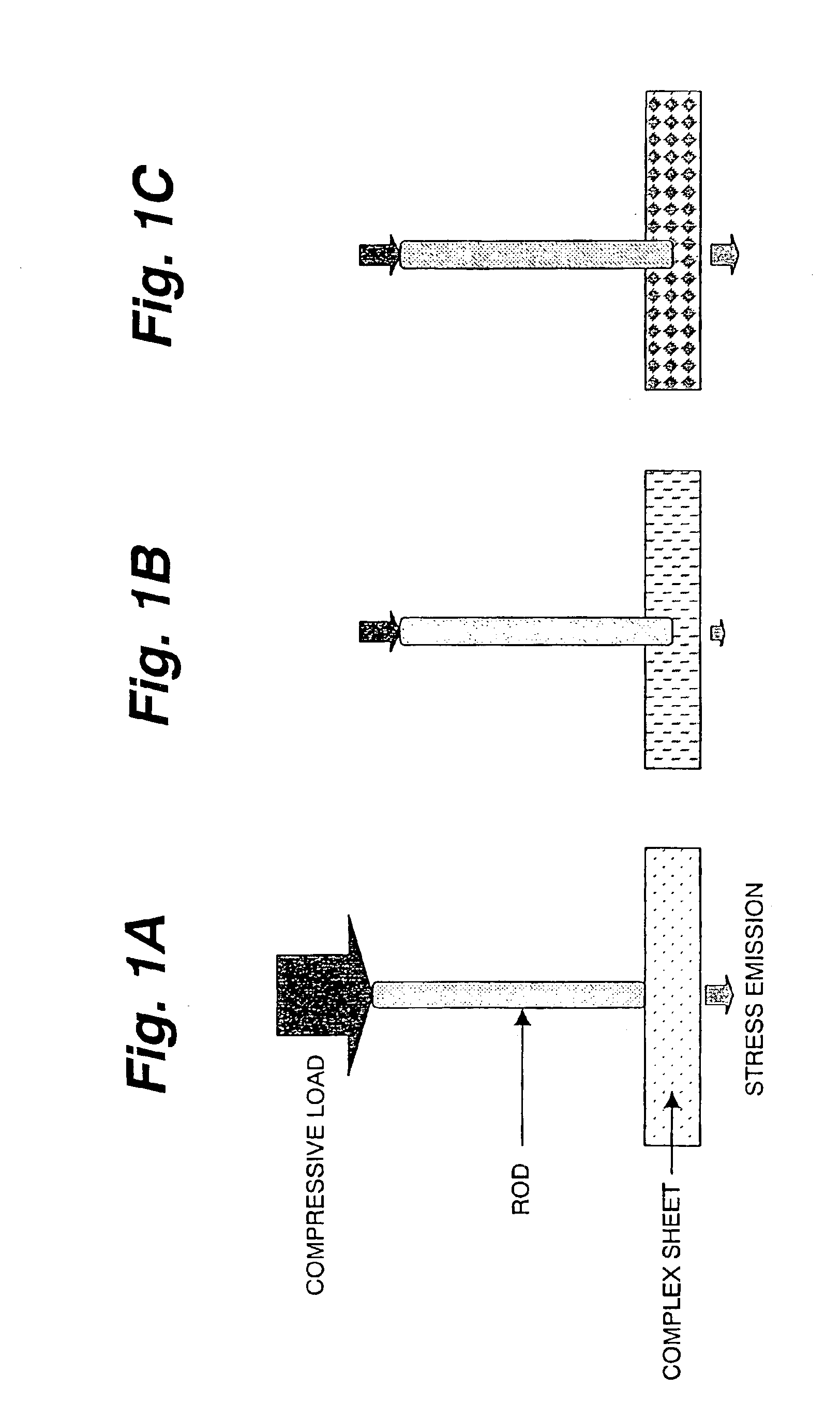
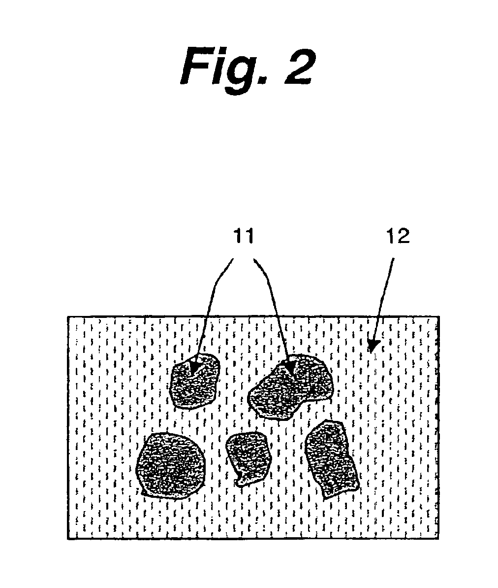
[0127]FIG. 2 shows a complex sheet according to the invention. As shown in FIG. 2, the complex sheet is a sheet of a complex material of stress emission particles 11 of SrAl2O4:Eu and an elastic material 12. The elastic material 12 is a soft organic material having a Young's modulus smaller than 10 MPa, preferably equal to or smaller than 1 MPa, or more preferably equal to or smaller than 0.1 MPa, and normally not smaller than 0.0001 MPa. Practically, it may be silicone rubber, organic silicon compound having siloxane bonds, synthetic rubber, natural rubber, or the like. Weight percent of the stress emission particles 11 in the complex material is from equal to or more than 10% to less than 100%, preferably from equal t or more than 10% to less than 90%, or more preferably from equal to or more than 30% to equal to r less than 80%. Diameter of each stress emission particle 11 may be, for example, μm size or smaller. For example, it may be from equal to or smaller than 100 nm to equa...

second embodiment

[0149]Next explained is the invention.

[0150]In the second embodiment, surfaces of the stress emission particles 11 are coated by silica 13 as shown in FIG. 8. Then, after the surface of the silica 13 is treated with a silane coupling agent, the stress emission particles are complexed with the elastic material 12. The other features of the first embodiment are common to those of the first embodiment. Therefore, their explanation is omitted here.

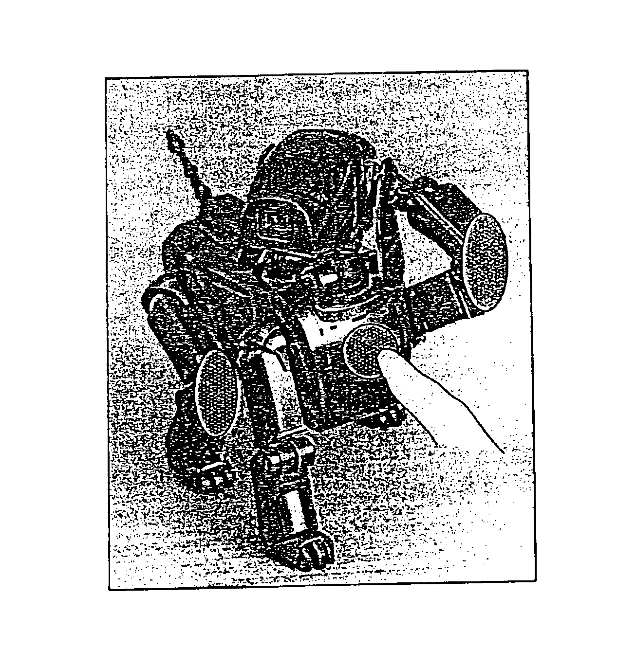
[0151]According to the second embodiment, the silica 13 coating the surfaces of the stress emission particles 11 binds more firmly with the silane coupling agent than the stress emission particles 11 themselves. Therefore, the second embodiment enhances adhesion between the stress emission particles 11 and the elastic material 12, and therefore allows easier emission of light with a light hand or finger touch of a person to the complex sheet.

third embodiment

[0152]Next explained is the invention.

[0153]The first and second embodiments rely on application of a pressure to the complex sheet to bring about emission of light. The third embodiment, however, is directed to stretching the complex sheet in parallel to its surface for bringing about emission of light.

[0154]More specifically, the third embodiment brings about stress emission by stretching the complex sheet identical to the first embodiment in parallel to its surface. The emission mechanism will be as explained below. When the complex sheet is stretched in parallel to its surface, it is compressed in thickness. Due to expansion in area of the complex sheet and its compression in thickness, a shear stress is generated on the interface between the stress emission particles 11 and the elastic material 12, or friction occurs between the stress emission particles 11 and the elastic material 12 or between the stress emission particles 11 themselves. As a result, light is emitted.

[0155]Ne...


PUM

PropertyMeasurementUnit
mean diameteraaaaaaaaaa
Young's modulusaaaaaaaaaa
thicknessaaaaaaaaaa

Abstract

A complex material, which emits light with a light hand or finger touch of a person and only when subjected to a stress, comprises stress emission particles and an elastic material. The stress emission particles such as SrAl2O4:Eu particles emit light when subjected to a stress. The elastic material is a soft material having a Young's modulus smaller than 10 MPa, such as silicone rubber, synthetic rubber, natural rubber, or the like. Weight percent of the particles in the complex material is from equal to or more than 10% to less than 100%, ore preferably from equal to or less more than 10% to equal to or less than 90%. The particles are preferably surface-treated by a silane coupling agent. The complex material is used as an artificial light-emitting skin or an artificial light-emitting body.

Description

BACKGROUND OF THE INVENTION[0001]1. Field of the Invention[0002]This invention relates to a complex material, artificial light-emitting skin and artificial light-emitting body that are suitable for use, for example, in the field of entertainment or amusement using emission of light effectively.[0003]2. Description of the Related Art[0004]For years, aluminate compound materials doped with rare earth elements have been remarked as fluorescent materials, and have been under vigorous researches. Among various aluminate compound materials, Eu-doped SrAl2O4 (named SrAl2O4:Eu herein below) has attracted the greatest attention as from a report on the phenomenon of stress emission as introduced herein below. Thus, prehistory of researches and developments of this SrAl2O4:Eu is first explained below while citing prior art documents.History of Patents and Researches of SrAl2O4:Eu as Fluorescent Material[0005]SrAl2O4:Eu has the prehistory of having been studies as a fluorescent material from a ...

Claims


Application Information

Patent Timeline
Patent Type & Authority Patents(United States)
IPC IPC(8): C09K11/06F21K2/00F21K2/04G01N21/70G01N21/62A61F13/02C09K11/00C09K11/02C09K11/08C09K11/64
CPCC09K11/06F21K2/04C09K11/7734G01N21/70Y10T428/25
Inventor TOYODA, JUNICHISUZUKI, MASAYUKINAGASAWA, NAOMI
Owner SONY CORP
Why Eureka
Try Eureka