Self-powered wireless switch

a self-powered, wireless switch technology, applied in the direction of generator/motor, anti-theft devices, transportation and packaging, etc., can solve the problems of complex array of wire harnesses, the proliferation of components required to implement new features is becoming difficult to manage from cost, serviceability and packaging perspectives, and no major automotive program has received large benefits from this technology

Inactive Publication Date: 2005-08-23
MASSACHUSETTS INST OF TECH +1
View PDF81 Cites 107 Cited by
  • Summary
  • Abstract
  • Description
  • Claims
  • Application Information

AI Technical Summary

Benefits of technology

[0008]It is therefore an object of the present invention to provide a wireless switch arrangement that generates its own electrical power to remove any need for a direct connection to a battery or other external source of electrical power.
[0009]It is another object of the present invention to provide a wireless switch having a local energy harvesting arrangement dedicated to the switch circuit to remove any need for an external power supply wire connection to the switch.
[0012]Thus, the present invention provides a switch arrangement that can be located without regard to insuring accessability of a wiring harness or connector. This freedom to locate a switch anywhere without being confined by a wire harness reduces the complexity of the power distribution system in such applications as automobiles, aircraft and HVAC equipment.

Problems solved by technology

This conventional technology is characterized by very complex arrays of wire harnesses, interconnecting switches, motors, relays, electronic modules and the like.
The proliferation in the quantity of the components required to implement new features is becoming difficult to manage from cost, serviceability and packaging viewpoints.
However, to date, no major automotive program has received large benefits from this technology.
The necessity of supplying power from a vehicle battery 20 to each of the switches, controller, and loads generally results in a very complex electrical distribution system.
As the number of systems on a vehicle increase, the complexity of the distribution as well as the bulk of associated wiring harnesses increases.
However, the need to supply electrical power still requires the use of a wiring harness, thereby negating much of the advantage gained by using a wireless communication system.
In other words, a maximum reduction in the number of wires to zero will not be achieved, while full freedom to locate a switch anywhere in the vehicle will not be attained.
The use of a dedicated battery to provide power locally at individual switches can eliminate the need for power supply wires, but conventional batteries have a limited life.
Thus, continual battery replacement becomes a major drawback, particularly in vehicle applications where a large number of switches are used.

Method used


Image

  • Self-powered wireless switch
  • Self-powered wireless switch
  • Self-powered wireless switch

Examples


first embodiment

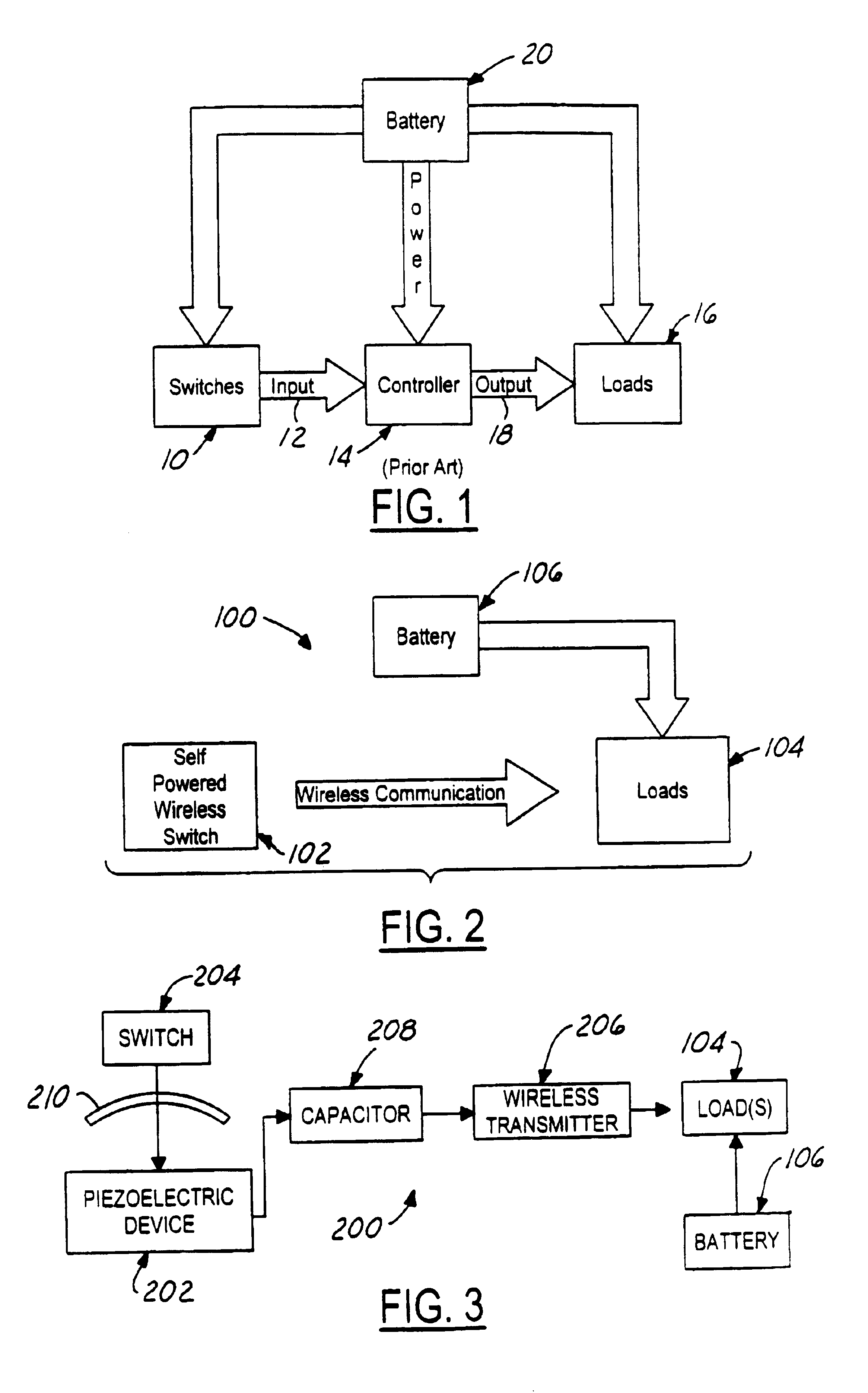
[0029]Referring now to FIG. 3, a self-powered wireless switch arrangement 200 is shown in accordance with the present invention. More specifically, a piezoelectric switch element 202 is arranged to be actuated by a user via a switch handle or button 204. The switch handle operates to apply a mechanical force to deflect or distress the piezoelectric element, which in turn includes a piezoelectric material (for example, PZT-lead zirconate titanate) that operates to convert the mechanical force into an output electric voltage and current. The generated electric power can be directly connected to a wireless transmitter circuit 206, or stored by a capacitor 208. The capacitor would then become the power source for operation of wireless transmitter circuit 206.

[0030]The wireless transmitter circuit can be implemented using RF, infrared, ultrasonic and other wireless technologies known to one of ordinary skill in the art. For example, a 13.6 MHz transmitter circuit can be provided that onl...

second embodiment

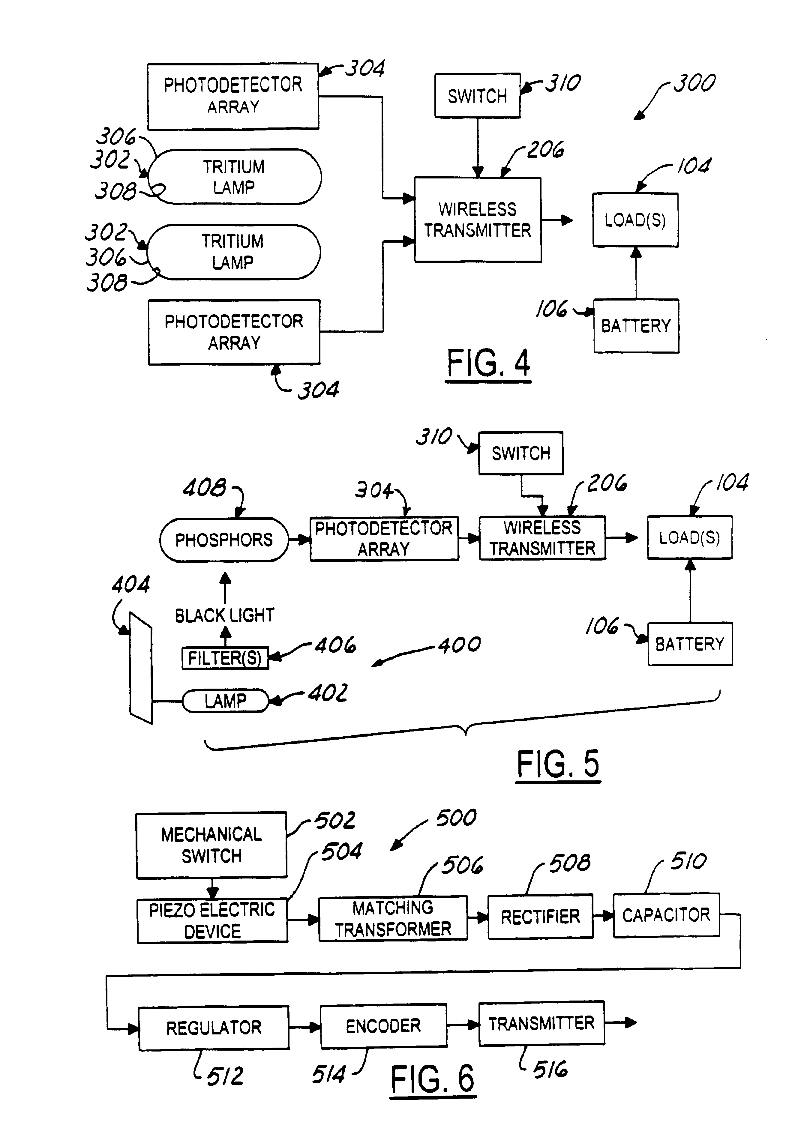
[0033]Referring now to FIG. 4, a self-powered wireless switch 300 is shown in accordance with the present invention, where like elements to the previous embodiment have been denoted with the same reference number. In this embodiment, the energy harvesting arrangement uses at least one tritium lamp 302 and a photovoltaic device 304 to power the wireless transmitter circuit 206. The tritium lamp provides a lightweight, long life energy source. For example, these lamps are now being used to illuminate exit signs on airplanes and watch dials. Tritium has a half-life of 12.4 years and decays to helium by releasing a beta particle with a maximum energy of 18.6 keV. This energy is approximately equal to the energy of the electrons in a television tube. Thus, the products of tritium decay, i.e., stable helium and electrons, can be contained within a glass sphere 306. The released beta particles have sufficient energy to excite phosphors 308 that can be coated on the inside of the glass sphe...

embodiment 400

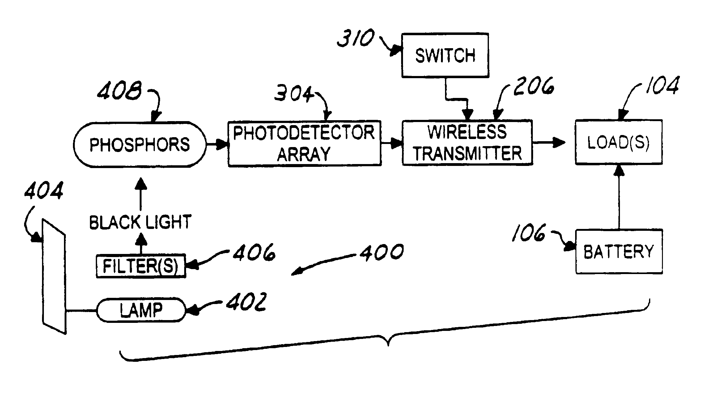
[0037]In an alternative embodiment 400 shown in FIG. 5, the basic tritium power source is replaced with a black light source. For example, in an automobile, the interior could be illuminated with black light via a bulb 402 located in a headliner 404. A conventional bulb produces black light (UV), and one or more filters 406 can be used to eliminate the visible portion of the optical spectrum. Thus, the black light is invisible to the driver, but can be used to excite phosphors 408 to illuminate switch 310 and simultaneously excite photo detectors 304. Visible light could also be used, but depending on the location, could be a distraction to a vehicle occupant, especially at night. For some applications, generating electrical power via black light or mechanical motion may be more attractive in terms of cost than using the tritium-based power source.

[0038]Thus, the self-powered wireless switch of the present invention allows a finger actuated switch to provide sufficient power to oper...


PUM


Abstract

A wireless switch is provided having a twenty-year life energy harvesting arrangement for self-powering a wireless transmitter. The energy harvesting arrangement is implemented in one embodiment using a piezoelectric switch element. A tritium light source and photovoltaic device are used in a second embodiment, while a black light source and photovoltaic device are used in a third embodiment. The energy harvesting wireless switch arrangement of the present invention can be combined, for example, with a vehicle side mirror switch, to reduce the complexity of the wire harness feeding the door. The wireless switch can be located without regard to accessability of a wiring harness or connector.

Description

[0001]This application is a continuation-in-part of application Ser. No. PCT / US01 / 31908 filed Oct. 12, 2001, published under PCT Article 21(2) in English, which is a continuation of application Ser. No. 09 / 949,195 filed Sep. 7, 2001, now abandoned, which is a continuation-in-part of application Ser. No. 09 / 687,400 filed Oct. 13, 2000, now abandoned. This application is a continuation-in-part of application Ser. No. 09 / 949,150 now U.S. Pat. No. 6,700,310 filed on Sep. 7, 2001.TECHNICAL FIELD[0002]The present invention generally relates to wireless switches, and more particularly to a wireless switch such as for use in an automobile or aircraft environment which does require a separate source of electrical power and associated wiring. The present invention also relates to wireless switches for use in other environments and applications.BACKGROUND ART[0003]During the last decade, the automotive industry has experienced very significant growth in the electrical / electronic content of aut...

Claims


Application Information

Patent Timeline
Patent Type & Authority Patents(United States)
IPC IPC(8): B60R25/00H02N2/00H02N2/18
CPCB60R25/24H01H2239/076H01H2300/03
Inventor MORRISON, GERALD O.MAUE, H. WINSTONSKARB, BRIAN P.BERTA, MICHAEL J.MEINZER, RICHARDPARADISO, JOSEPHFELDMEIER, MARKYOUNGS, JOHN
Owner MASSACHUSETTS INST OF TECH
Why Eureka
Try Eureka