
Apparatus and method for improved chopping mixer

a mixer and mixer technology, applied in the field of radio frequency circuitry, can solve the problems of differential circuits having infinite attenuation to and the undesired spectral component of second order intermodulation distortion (im2)

Inactive Publication Date: 2005-08-23
APPLE INC
View PDF10 Cites 33 Cited by
  • Summary
  • Abstract
  • Description
  • Claims
  • Application Information

AI Technical Summary

Benefits of technology

The present invention provides a chopping mixer and a method of operating it. The chopping mixer has a unique design that allows for efficient mixing of signals. The technical effect of this invention is improved signal quality and reliability in electronic devices.

Problems solved by technology

Because of limited narrow band selectivity, second order intermodulation distortion (IM2) presents an undesired spectral component within the signal band of interest.
In theory, differential circuits have infinite attenuation to second order intermodulation distortion; however, in reality this is far from the truth, due in no small part to device mismatches, parametric imbalance, imperfect layout, and other device characteristic inequalities that cause imbalances which provide a lower than desired second order input intercept point (IIP2).

Method used


Image

  • Apparatus and method for improved chopping mixer
  • Apparatus and method for improved chopping mixer
  • Apparatus and method for improved chopping mixer

Examples


Embodiment Construction

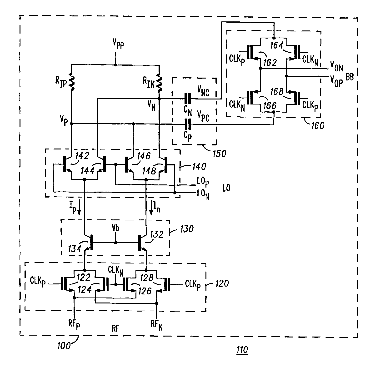
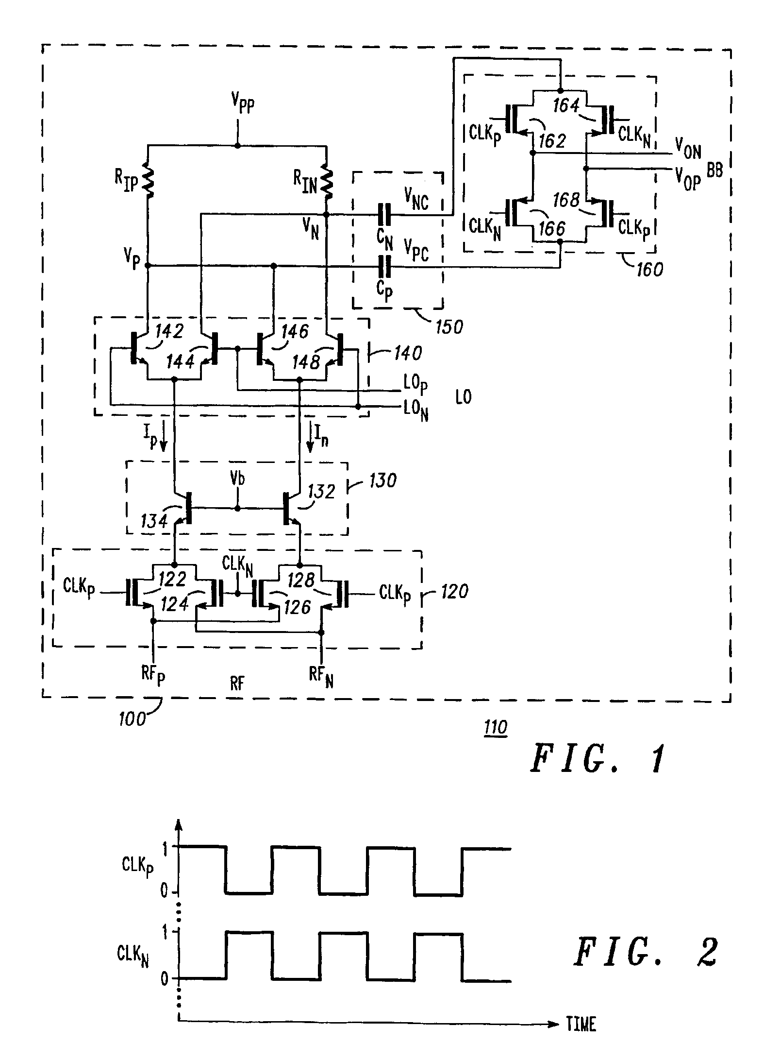
[0012]Referring firstly to FIG. 1, an AC chopping mixer 100 for use in a direct conversion radio receiver 110 is shown. The mixer 100 has an input chopper cell 120 constituted of two pairs of MOSFET chopper transistors 122&124 and 126&128. The chopper transistors 122-128 are coupled to receive chopper clock signals clkp and clkn (see FIG. 2) and cross-coupled differential input signals RFp and RFn at an RF input port. The input chopper cell 120 produces chopped differential voltage output signals Vip and Vin.

[0013]A voltage-current (V-I) converter 130 is constituted of bipolar transistors 132 and 134 that have their base electrodes commonly coupled to receive a bias voltage Vb. Outputs from the chopper transistors 122-128 of the input chopper cell 120 are connected respectively to emitter electrodes of the bipolar transistors 132 and 134 in the voltage-current converter 130, so that the transistors sink at their collector electrodes currents Ip and In that are proportional to respec...


PUM


Abstract

An apparatus and method for an improved chopping mixer (100) having a bipolar mixer stage (140) for mixing signals (lp, In, LOp, LOn) received thereby; an output chopping stage (160); and an AC coupling stage (150) for coupling the mixed signal to the output chopping stage. The signal prior to the chopping output stage is centered at the chopping clock frequency rather than DC. AC coupling allows removal of common mode signal in a desired frequency range. Also, the second order component present on each single ended output will also be DC blocked by the AC coupling capacitors, resulting in improved second order IP2 performance.

Description

FIELD OF THE INVENTION[0001]This invention relates to chopping mixers, and particularly (though not exclusively) to radio frequency circuitry such as direct conversion receivers.BACKGROUND OF THE INVENTION[0002]In the field of this invention it is known to use direct conversion or zero-IF receivers in radio receivers for applications such as cellular telephony. In such receivers, it is necessary to maintain the spectral purity of the channel used for reception. Because of limited narrow band selectivity, second order intermodulation distortion (IM2) presents an undesired spectral component within the signal band of interest. This occurs when two or more interfering signals, whose difference in frequency is less than the IF bandwidth of the desired signal, mix with one another due to some second order nonlinearity and produce a baseband spectral component. To minimize the effects of second order intermodulation within critical circuit blocks in the signal path, it is known in the art...

Claims


Application Information

Patent Timeline
Patent Type & Authority Patents(United States)
IPC IPC(8): H03D7/14H04B1/30
CPCH03D7/14H04B1/16
Inventor KHLAT, NADIMLORENZO-LUACES, EDDIEBASTANI, BABAK
Owner APPLE INC
Learn More