Acoustic reflector for a BAW resonator providing specified reflection of both shear waves and longitudinal waves

a technology of acoustic reflector and baw resonator, which is applied in the direction of piezoelectric/electrostrictive/magnetostrictive devices, piezoelectric/electrostriction/magnetostriction machines, etc., can solve the problems of weak acoustic wave damping, viscous loss is unlikely to represent a limiting factor, and the resonance frequency performance is improved

Active Publication Date: 2005-08-23
AVAGO TECH INT SALES PTE LTD
View PDF7 Cites 148 Cited by
  • Summary
  • Abstract
  • Description
  • Claims
  • Application Information

AI Technical Summary

Benefits of technology

[0041]Starting from this prior art, it is the object of the present invention to provide a BAW

Problems solved by technology

Although these values are sufficient to keep pace with SAW devices (SAW=surface acoustic wave) for applications in the mobile phone area, these values are barely sufficient enough to produce, for example, antenna duplexers or other demanding low-loss/high-selectivity filters, e.g. US-CDMA filters or W-CDMA filters.
Duplexers available on the market today are large ceramic components because the SAW filters do not have sufficient power handling capability.
CDMA filters are often made by so-called “split-band” SAW filters using two filters connected in parallel with different center frequencies, because a single SAW filter would not have sufficiently steep transition characteristics.
Viscous losses are unlikely to represent a limiting factor, because secondary acoustic modes in the resonators very often have very high Q-factors that would not be present if the materials themselves would cause a strong damping of the acoustic waves.
Interferometric measurements have shown that part of the energy is also lost by lateral acoustic waves, which means that the energy trapping does not work perfectly.
Shear waves are not excited in ideal, infinitely large resonators, because there is no piezoelectrical coupling between a vertical electrical field and the shear stresses in a piezo layer with a dominant C-axis crystal orientation.
(a) In the piezoelectric layer of the BAW resonator, tilted grain boundaries may occur. If this tilt has even a small portion of a preferred direction, then a vertical field may lead to launch of shear waves in the piezoelectric layer.
(b) At the edges of

Method used


Image

  • Acoustic reflector for a BAW resonator providing specified reflection of both shear waves and longitudinal waves
  • Acoustic reflector for a BAW resonator providing specified reflection of both shear waves and longitudinal waves
  • Acoustic reflector for a BAW resonator providing specified reflection of both shear waves and longitudinal waves

Examples


Embodiment Construction

[0060]In the following description of the preferred embodiments, similar elements in the individual drawings are provided with similar or the same reference numerals.

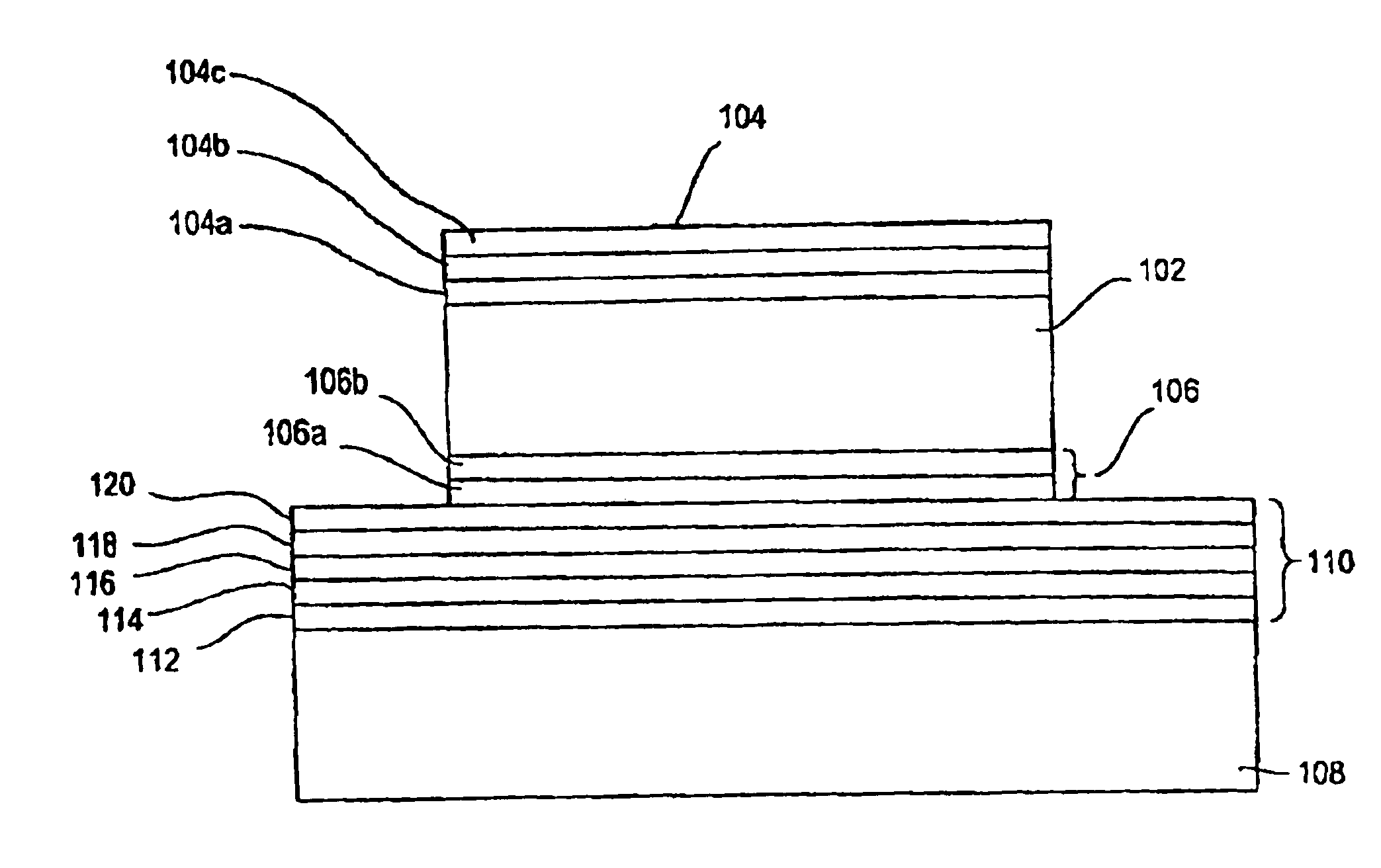
[0061]The present invention provides acoustic mirrors or acoustic reflectors for BAW resonators, which lead to significant improvement of the Q-factor. BAW resonators having the inventive acoustic reflectors are necessary in particular for applications requiring Q-factors larger than 700, such as the above-mentioned employment in antenna duplexers and other filter applications requiring low losses and high selectivity, for example the mentioned US-CDMA filters or W-CDMA filters.

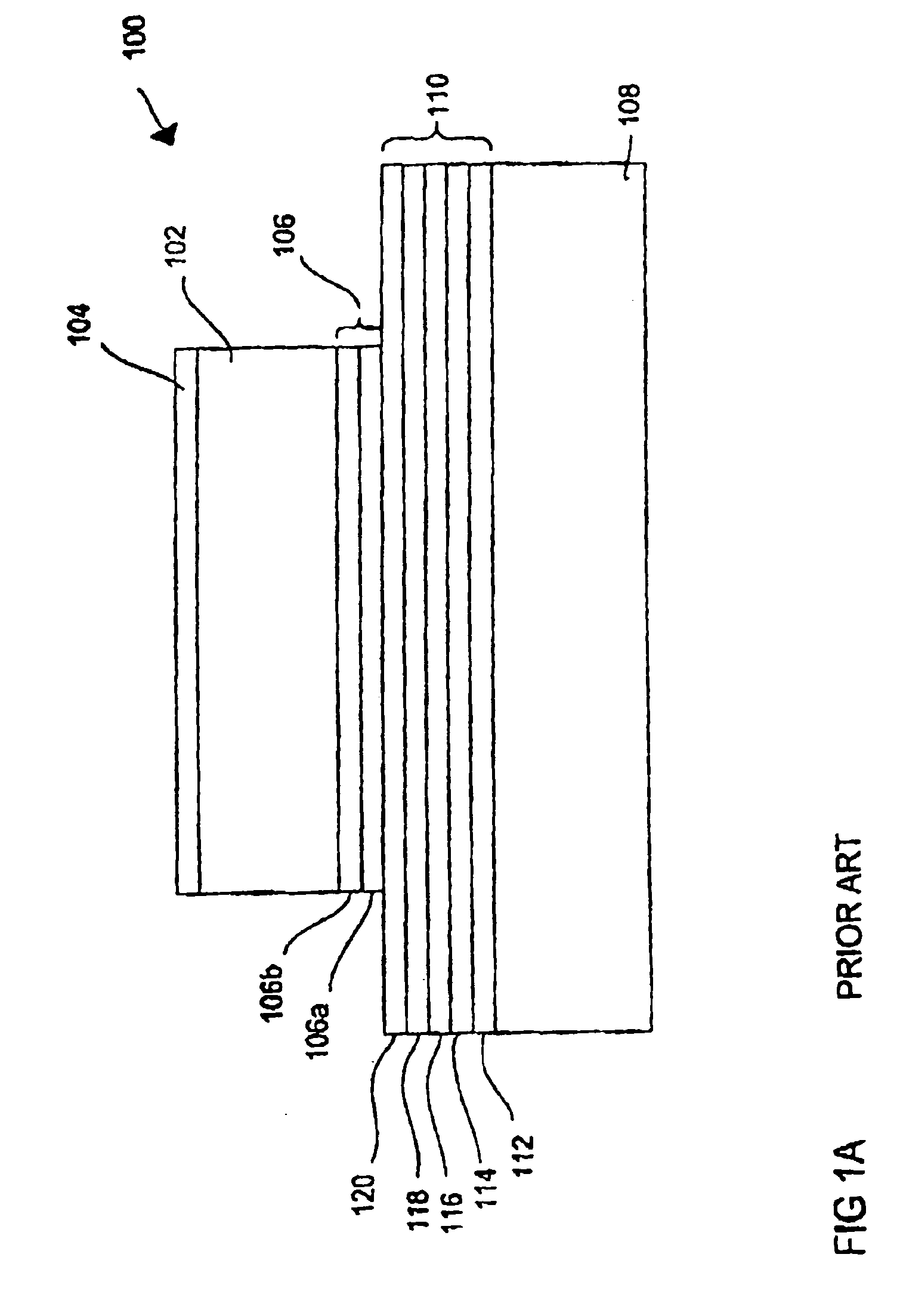
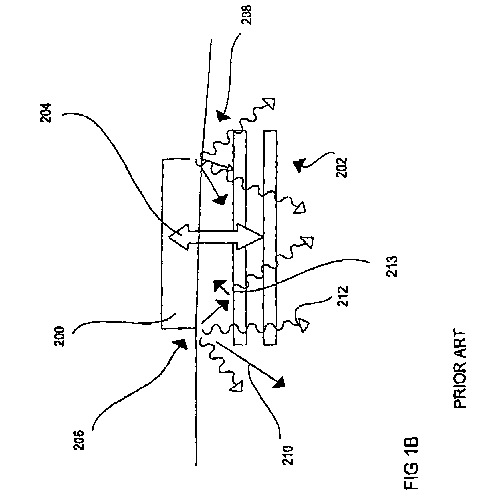
[0062]According to the invention, an improved acoustic reflector / acoustic mirror is provided, which avoids the leakage of acoustic energy (acoustic leakage) in the vertical direction, i.e. in the direction in which the individual layers of the element are disposed on top of each other.

[0063]According to a first preferred embodiment of the present...


PUM


Abstract

A BAW resonator includes a piezoelectric layer, a first electrode, a second electrode, a substrate, and an acoustic reflector disposed between the substrate and the second electrode. The acoustic reflector has a plurality of layers. A performance of the acoustic reflector is determined by its reflectivity for a longitudinal wave existing in the BAW resonator at the resonance frequency of the BAW resonator and by its reflectivity for a shear wave existing in the BAW resonator at the resonance frequency of the BAW resonator. The layers of the acoustic reflector and layers disposed between the acoustic reflector and the piezoelectric layer are selected, with reference to their number, material, and thickness, such that the transmissivity for the longitudinal wave and the transmissivity for the shear wave in the area of the resonance frequency is smaller than −10 dB.

Description

BACKGROUND OF THE INVENTION[0001]1. Field of the Invention[0002]The present invention relates to an acoustic reflector (acoustic mirror) for a BAW resonator (BAW=bulk acoustic wave), and here in particular to an acoustic reflector with a plurality of layers for an improved performance of the BAW resonator.[0003]2. Description of the Related Art[0004]The present invention preferably involves BAW filters for RF applications, and here in particular BAW filters for RF applications in which excellent selectivity and steep transition bands are required. In such filters, the most critical parameters are the quality factor and the coupling coefficient of the BAW resonators. The coupling coefficient is defined by the frequencies at which series resonance and parallel resonance occur. The coupling coefficient is a function of the electromechancial coupling of the piezoelectric layer of the BAW resonator as well as the thickness and types of materials uses in the overall arrangement of the BAW...

Claims


Application Information

Patent Timeline
IPC IPC(8): H03H9/00H03H9/17H03H9/56H03H9/58
CPCH03H9/175H03H9/56
Inventor MARKSTEINER, STEPHANFATTINGER, GERNOTAIGNER, ROBERTKAITILA, JYRKI
Owner AVAGO TECH INT SALES PTE LTD
Why Eureka
Try Eureka