
Digital/analog converter circuit with a device for compensating nonlinear distortions

a nonlinear distortion and digital/analog converter technology, applied in the field of digital/analog converter circuits, can solve the problems of feedback circuits, nonlinear distortions inevitably arise when converting the digital and the conversion of the pwm signal into the analog signal may experience nonlinear distortions

Inactive Publication Date: 2005-08-23
APPLE INC
View PDF7 Cites 13 Cited by
  • Summary
  • Abstract
  • Description
  • Claims
  • Application Information

AI Technical Summary

Benefits of technology

The solution effectively minimizes nonlinear distortions and stabilizes the converter circuit, allowing it to handle various pulse width modulated signals, including pseudo natural pulse width modulation, and provides a simple, stable method for compensating for analog circuit nonlinearities, resulting in a distortion-free analog output.

Problems solved by technology

Both the PCM / PWM conversion and the conversion of the PWM signal into the analog signal may experience nonlinear distortions.
In contrast, nonlinear distortions inevitably arise when converting the digital PWM signal into the analog signal.
These distortions are caused primarily by the “memory” of the analog area of the circuit in question.
Such “memory” properties of an analog circuit are system inherent and cannot be eliminated completely.
A drawback of this digital / analog converter circuit is that it is designed exclusively for UPWM (uniform sampling pulse width modulated) signals.
A drawback of feedback circuits is the instabilities they cause.

Method used


Image

  • Digital/analog converter circuit with a device for compensating nonlinear distortions
  • Digital/analog converter circuit with a device for compensating nonlinear distortions

Examples


Embodiment Construction

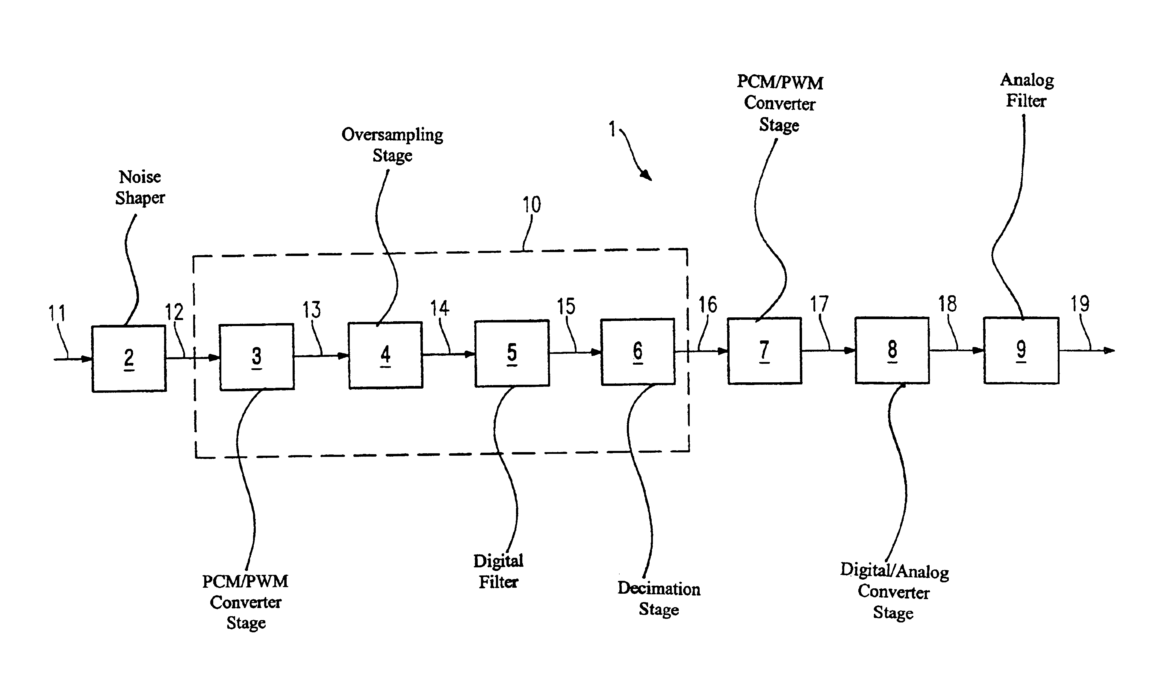
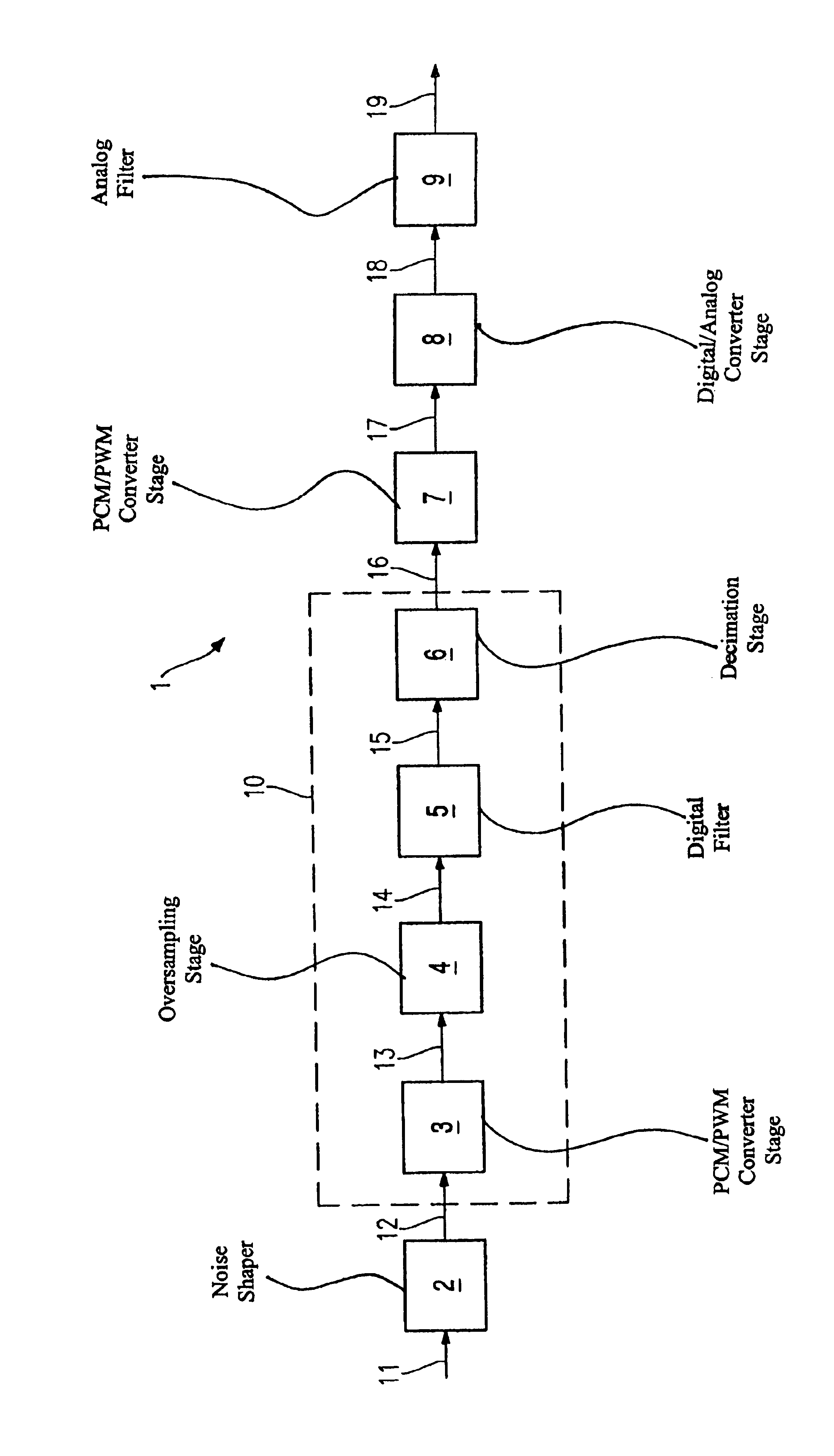
[0043]The FIGURE shows the block diagram of a digital / analog converter circuit 1, where the signal path contains a noise shaper 2, a PCM / PWM converter stage 3, an oversampling stage 4, a digital filter 5, a decimation stage 6, a PCM / PWM converter stage 7, a digital / analog converter stage 8 and an analog filter 9 in the stated order. The PCM / PWM converter stage 3, the oversampling stage 4, the digital filter 5 and the decimation stage 6 together form a precompensation stage 10. A digital PCM signal 11 is fed into the input side of the noise shaper 2. Next, the PCM signal 12 which is output from the noise shaper 2 is converted into a digital PWM signal 13. The signal rate is increased using the oversampling stage 4. The resultant PCM signal 14 is filtered using the digital filter 5. The signal rate of the filtered PCM signal 15 is reduced again by the decimation stage 6. The digital PCM signal 16 has nonlinear distortions with respect to the digital PCM signal 11 on account of the dig...


PUM


Abstract

A digital / analog converter circuit (1) comprises a precompensation stage (10), a PCM / PWM converter stage (7) and a digital / analog converter stage (8), these components being arranged in the signal path in the stated order. The transfer function of the precompensation stage (10) is designed such that the analog output signal (19) is essentially proportional to the digital PCM input signal (11).

Description

CROSS REFERENCE TO RELATED APPLICATION[0001]This application is a continuation of copending International Application No. PCT / DE02 / 03174 filed Aug. 29, 2002 which designates the United States, and claims priority to German application no. 101 55 426.5 filed Nov. 12, 2001.TECHNICAL FIELD OF THE INVENTION[0002]The present invention generally relates to a digital / analog converter circuit which can be used to convert digital PCM signals into analog signals without any distortion.DESCRIPTION OF RELATED ART AND BACKGROUND OF THE INVENTION[0003]In many technical systems, digital signals are converted into analog signals using pulse width modulations. Examples of such systems are engine controllers, calibration circuits, switched mode power supplies, DC voltage converters, digital amplifiers and, in particular, digital audio amplifiers.[0004]In the aforementioned systems, the digital signal is normally available on the input side in the form of a PCM (pulse code modulated) signal and is fir...

Claims


Application Information

Patent Timeline
Patent Type & Authority Patents(United States)
IPC IPC(8): H03K7/00H03M1/06H03K7/08H03M1/82
CPCH03K7/08H03M1/0626H03M1/822
Inventor KRANZ, CHRISTIAN
Owner APPLE INC
Learn More