Thin film optical measurement system and method with calibrating ellipsometer

a thin film, optical measurement technology, applied in the direction of optical radiation measurement, instruments, polarisation-affecting properties, etc., can solve the problems of significant calibration error, affecting the accuracy of measured data, and reducing the accuracy of reference samples for accurate calibration

Inactive Publication Date: 2005-08-23
THERMA WAVE INC
View PDF96 Cites 30 Cited by
  • Summary
  • Abstract
  • Description
  • Claims
  • Application Information

AI Technical Summary

Benefits of technology

[0009]The present invention is a thin film optical measurement system with a wavelength stable calibration ellipsometer that precisely determines the thickness of a film on a reference sample. The measured results from the calibration ellipsometer are used to calibrate other optical measurement devices in the thin film optical measureme

Problems solved by technology

Further, heat, contamination, optical damage, alignment, etc., that can occur over time in optical measurement devices, affect the accuracy of the measured results.
After fabrication, the reference sample is kept in a non-oxygen environment to minimize any further oxidation and contamination that changes the thickness of the reference sample film away from the known thickness, and thus reduces the effectiveness of the reference sample for accurate calibration.
For such thin

Method used


Image

  • Thin film optical measurement system and method with calibrating ellipsometer
  • Thin film optical measurement system and method with calibrating ellipsometer
  • Thin film optical measurement system and method with calibrating ellipsometer

Examples


Embodiment Construction

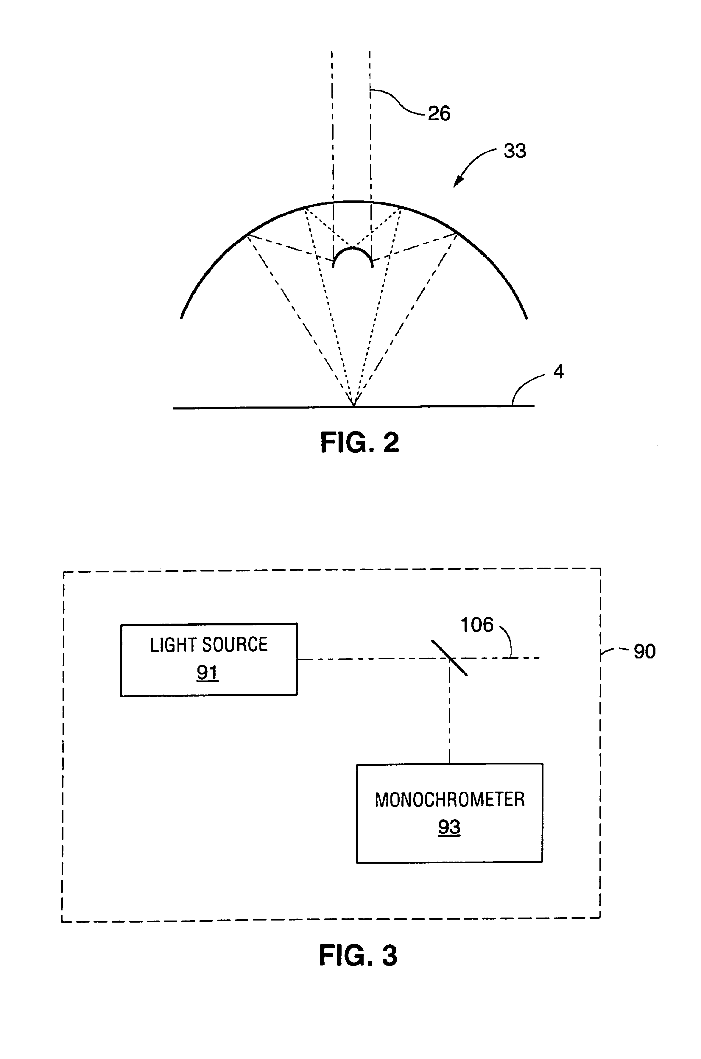
[0016]The present invention is a composite thin film optical measurement system 1 having a wavelength stable reference ellipsometer 2 that is used, in conjunction with a reference sample 4 having a substrate 6 and thin film 8 with known compositions, to calibrate non-contact optical measurement devices contained in the composite thin film optical measurement system 1.

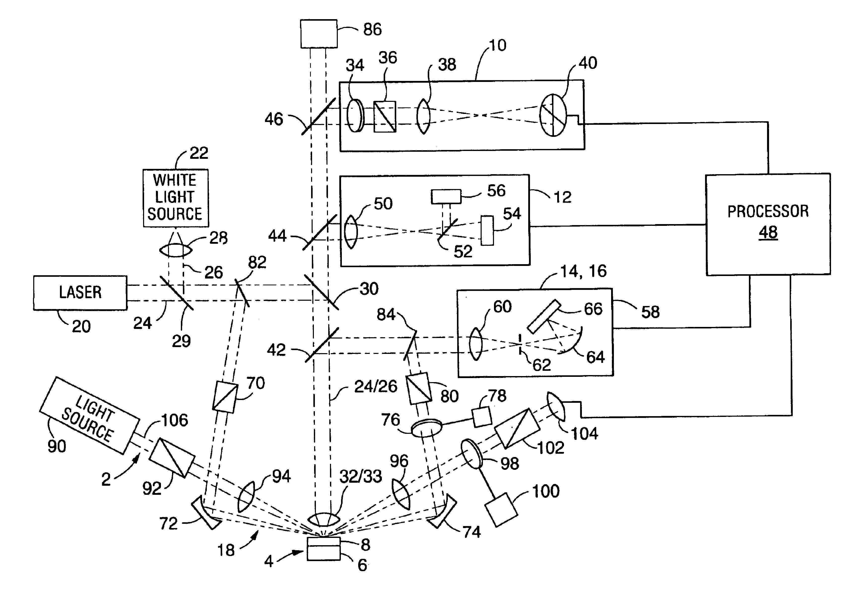
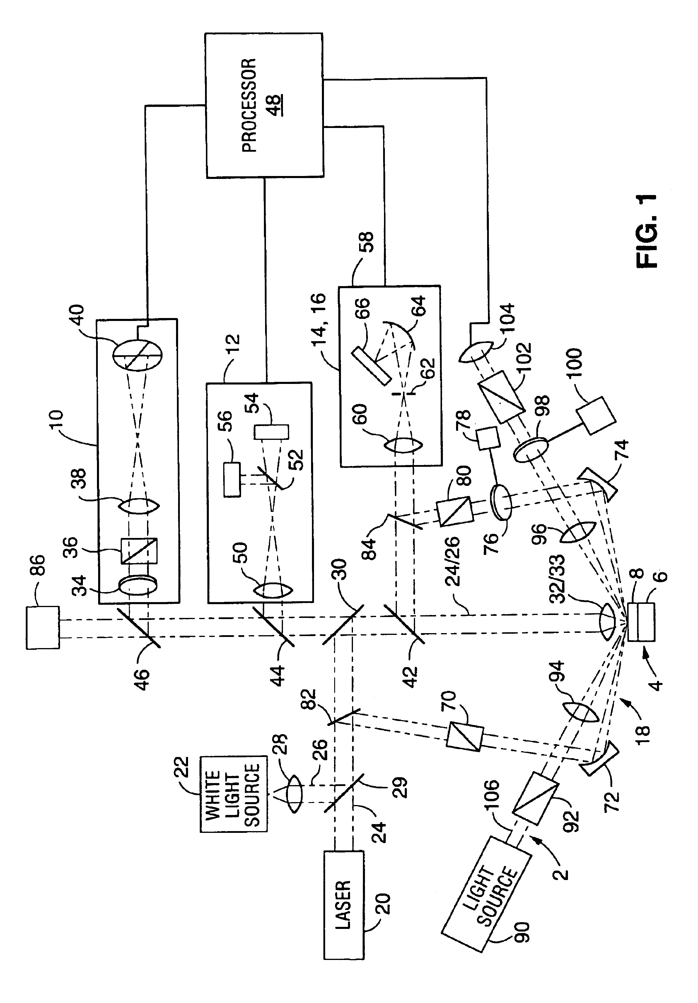
[0017]FIG. 1 illustrates the composite optical measurement system 1 that has been developed by the present assignees, which includes five different non-contact optical measurement devices and the reference ellipsometer 2 of the present invention.

[0018]Composite optical measurement system 1 includes a Beam Profile Ellipsometer (BPE) 10, a Beam Profile Reflectometer (BPR) 12, a Broadband Reflective Spectrometer (BRS) 14, a Deep Ultra Violet Reflective Spectrometer (DUV) 16, and a Broadband Spectroscopic Ellipsometer (BSE) 18. These five optical measurement devices utilize as few as two optical sources: laser 20 and white ...


PUM


Abstract

An optical measurement system for evaluating a reference sample, having at least a partially known composition, includes a reference ellipsometer and at least one non-contact optical measurement device. The ellipsometer includes a light generator, an analyzer, and a detector. The light generator generates a beam of quasi-monochromatic light of known wavelength and polarization, which is directed at a non-normal angle of incidence relative to the reference sample. The analyzer creates interference between S and P polarized components in the beam after interaction with the sample. The detector then measures the intensity of the beam, which a processor uses to determine the polarization state of the beam and, subsequently, an optical property of the reference sample. The processor then can calibrate an optical measurement device by comparing a measured optical parameter from the optical measurement device to the determined optical property from the reference ellipsometer.

Description

CLAIM OF PRIORITY[0001]The present application is a continuation of U.S. application Ser. No. 10 / 320,907, filed Dec. 17, 2002, now U.S. Pat. No. 6,753,962, which in turn is a continuation of U.S. application Ser. No. 10 / 138,984, filed May 3, 2002, now U.S. Pat. No. 6,515,746, which in turn is a divisional of U.S. application Ser. No. 09 / 886,514, filed Jun. 21, 2001, now U.S. Pat. No. 6,411,385, which is in turn a continuation of U.S. application Ser. No. 09 / 247,121, filed Feb. 8, 1999, now U.S. Pat. No. 6,304,326, which is in turn a continuation of U.S. application Ser. No. 09 / 098,880, filed Jun. 17, 1998, now U.S. Pat. No. 5,900,939, which is in turn a continuation of U.S. application Ser. No. 08 / 890,697, filed Jul. 11, 1997, now U.S. Pat. No. 5,798,837.FIELD OF THE INVENTION[0002]The present invention relates to optical analyzers, and more particularly to a thin film optical measurement system having a calibrating ellipsometer.BACKGROUND OF THE INVENTION[0003]There is considerable...

Claims


Application Information

Patent Timeline
IPC IPC(8): G01B11/06G01N21/21G01J4/00
CPCG01B11/0641G01J4/00G01N21/211
Inventor OPSAL, JONFANTON, JEFFREY T.UHRICH, CRAIG
Owner THERMA WAVE INC
Why Eureka
Try Eureka