Objective lens system

a lens system and objective technology, applied in the field of objective lens systems, can solve the problems of large overall dimensions, high production cost of optical systems, and relatively high design cost, and achieve the effect of low cost and flexible production

Inactive Publication Date: 2005-08-23
GUARDWARE SYST INFORMATIKAI
View PDF12 Cites 12 Cited by
  • Summary
  • Abstract
  • Description
  • Claims
  • Application Information

AI Technical Summary

Benefits of technology

[0009]The object of the invention is to create an objective lens system, particularly for a fingerprint reader apparatus product range having various print area sizes, which eliminates the disadvantages described above, can be produced flexibly and at a low cost, and furthermore creates an image of a quality and distortion very close to the physical resolution of the image detector applied.

Problems solved by technology

Because of the arrangement used therein, the optical system requires a very long optical path, which would result in large overall dimensions.
The special design of the prism and the special arrangement of optical elements, however, make this optical system expensive to produce.
This design is relatively costly due to its complexity.
It is the common disadvantage of these optical systems that due to the application of afocal imaging, adversely large overall dimensions are necessitated.
The telecentric imaging enables a relatively shorter optical path, but the use of aspherical lenses and the correcting lens system consisting of three lenses increase the production costs of these optical systems.
A further common disadvantage of the objective lens systems described above is that in the case of systems having various print area sizes, they do not make possible to provide a product range based on a uniform optical block and therefore manufactured at a relatively favourable price.

Method used


Image

  • Objective lens system
  • Objective lens system
  • Objective lens system

Examples


Embodiment Construction

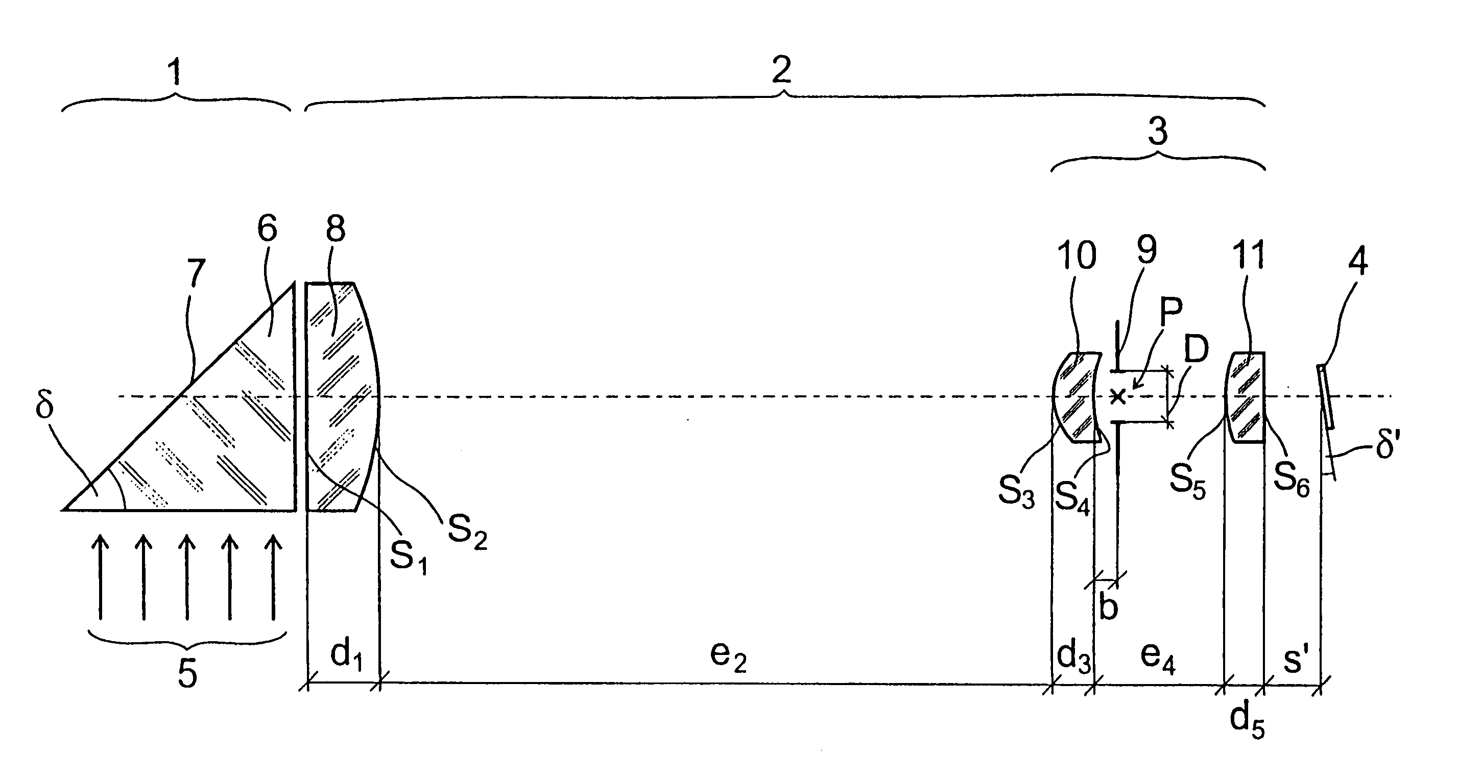
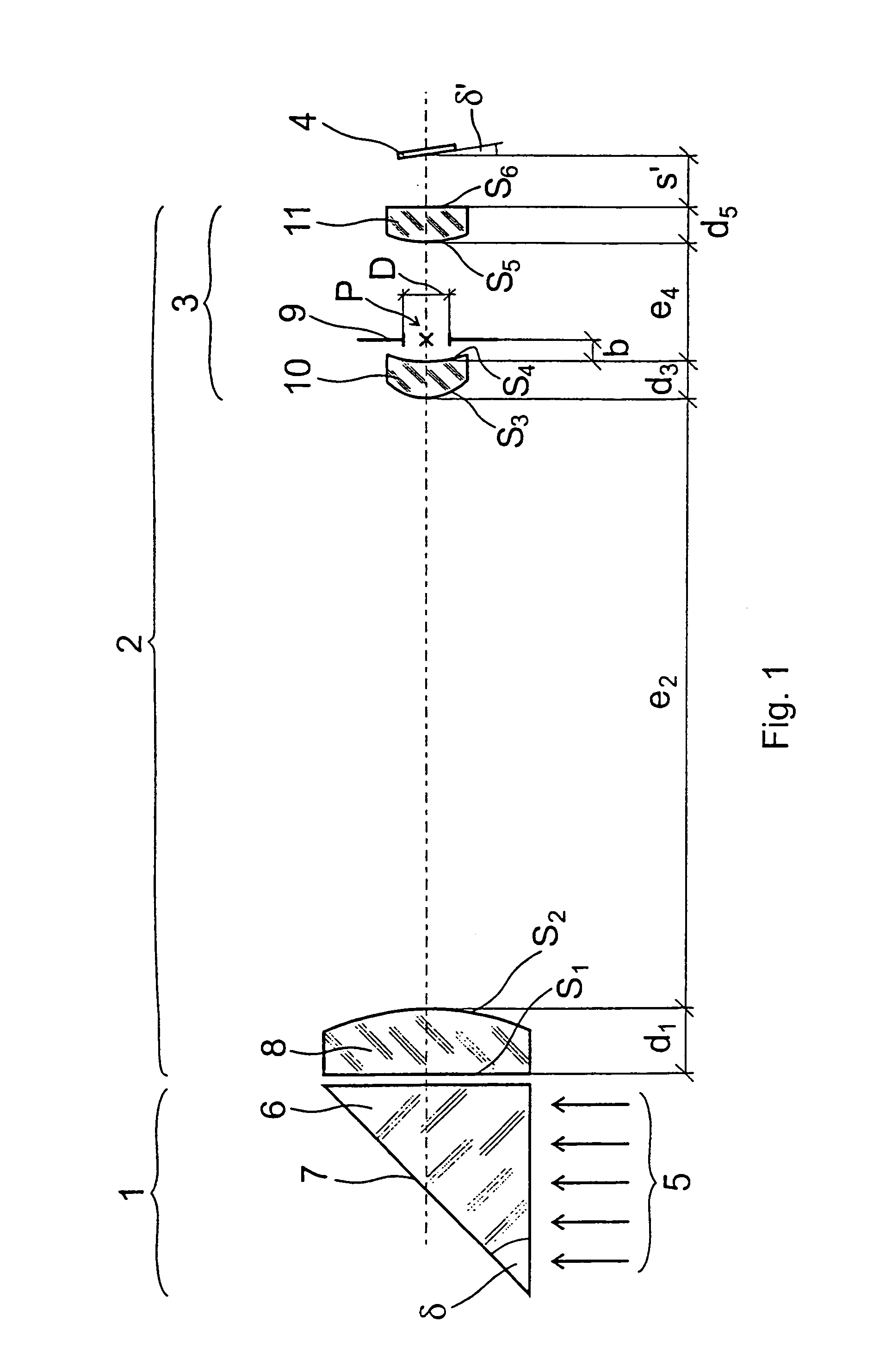
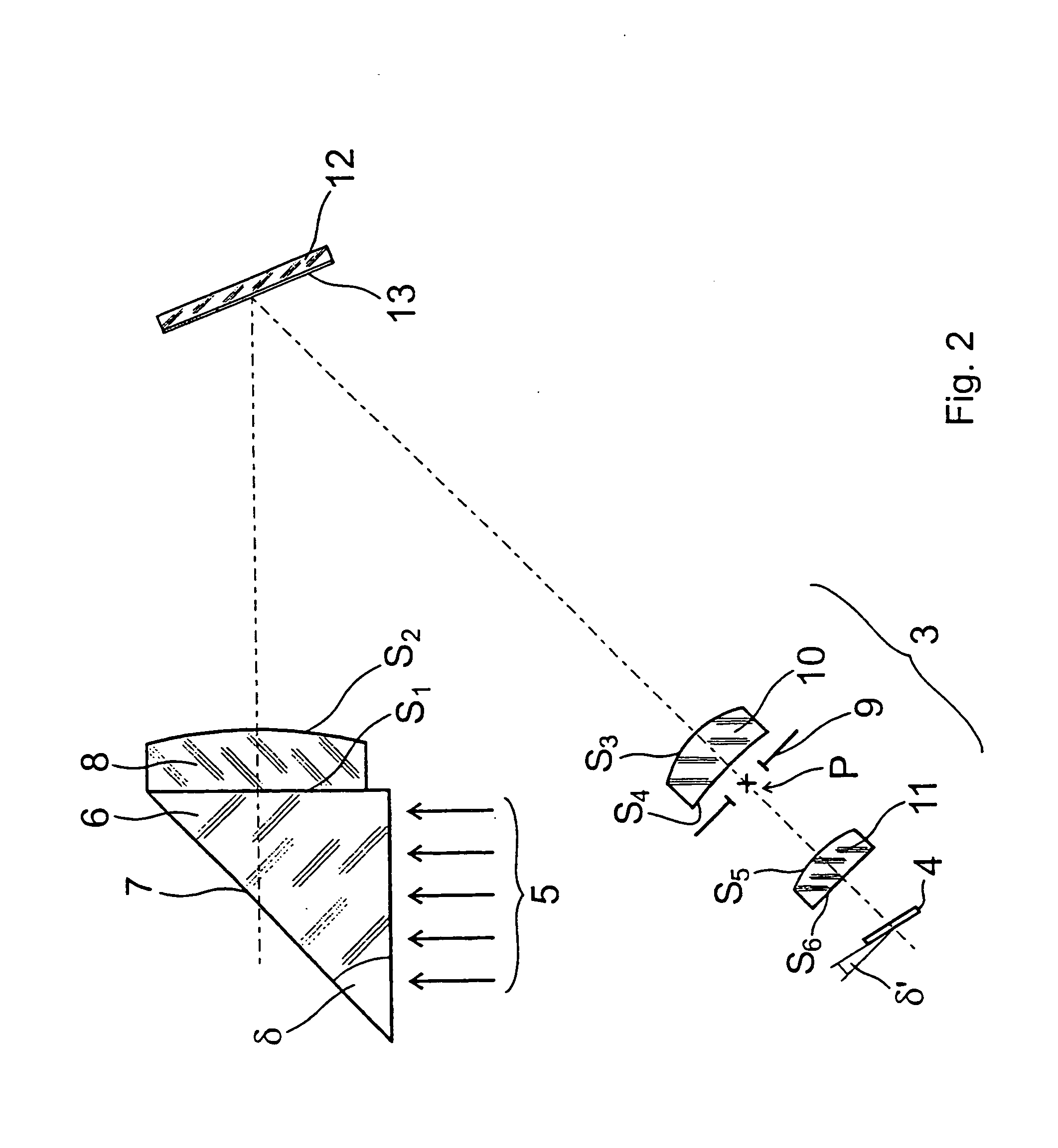
[0022]In FIG. 1, an objective lens system 2 arranged between a print imaging device 1 and a CMOS image sensor 4 is shown.

[0023]The print imaging device 1 comprises a prism 6 known per se, a total-reflecting surface of which represents a print area 7, on which a print of a finger in contact therewith appears. Through a light entering surface of prism 6, the print area 7 is illuminated with illumination 5 implemented preferably by one or more LED diodes, where the illumination has a narrow wavelength range, for example a 660 nm wavelength having a 20 to 40 nm half-width. At places where the finger is in contact with print area 7, the light of the illumination 5 is absorbed by the finger. From places, however, where the finger is not in contact with the print area 7, the light beams of the illumination 5 are totally reflected, they exit through the light exit surface of the prism 6, and by the objective lens system 2 according to the invention they are imaged onto image sensor 4. The p...


PUM


Abstract

An objective lens system (2), particularly for a fingerprint reader apparatus, said lens system (2) comprising a first lens (8) formed as a condensing lens guiding light beams arriving from an object generally telecentrically, an aperture stop (9) having a centre (P) and being located in the vicinity of a focal point of the first lens (8), a correcting second lens (10) arranged between the first lens (8) and the aperture stop (9) and juxtaposed with the aperture stop (9), and a correcting third lens (11) formed as a condensing lens and arranged beside the aperture stop (9) opposite the second lens (10). According to the invention, the second lens (10) is a condensing lens with a spherical surface (S3) facing the first lens (8), wherein the curvature centre of the surface (S3) is at a distance shorter than 15% of the curvature radius of the surface (S3) from the centre (P) of the aperture stop (9), and the aperture stop (9) is arranged at a distance shorter than 25% of the focal length of the first lens (8) from the focal point of the first lens (8).

Description

TECHNICAL FIELD[0001]The invention relates to an objective lens system, particularly for a fingerprint reader apparatus.BACKGROUND ART[0002]With the wide-spread application of identification on the basis of fingerprints, the requirements imposed on a fingerprint reader apparatus and especially on the objective lens system thereof are diverse. It is desired to produce such objectives simply and at a low cost. In addition, the optical image of the fingerprint should be projected by the objective lens system to the image detector with an image quality corresponding to the physical resolution of the image detector applied. From the aspect of low cost production, it is also desirable that the objective lens system allows simple adaptation to various print area sizes, the latter basically depending on the space limited by the size of the fingerprint reader apparatus and on the desired reliability of fingerprint identification.[0003]In a fingerprint reader apparatus, a total-reflection pri...

Claims


Application Information

Patent Timeline
Patent Type & Authority Patents(United States)
IPC IPC(8): G02B13/22G02B9/12G06K9/00G01B11/24G02B13/00G02B17/08G06T1/00
CPCG02B9/12G02B13/22G06K9/00046G06V40/1324
Inventor KALLO, PETER
Owner GUARDWARE SYST INFORMATIKAI
Why Eureka
Try Eureka