Single stage PFC and power converter unit

Active Publication Date: 2005-08-23
INFINEON TECH AMERICAS
View PDF1 Cites 16 Cited by
  • Summary
  • Abstract
  • Description
  • Claims
  • Application Information

AI Technical Summary

Benefits of technology

[0009]The present invention provides a single stage PFC and power converter for general purpose power supply for resonant loads. By modifying the circuit topology of the conventional half-bridge power converter, the present invention achieves efficiencies and reduced part counts that are improved over the conventional design.

Problems solved by technology

In the conventional power converter, the capacitor in the boost converter was operated to

Method used


Image

  • Single stage PFC and power converter unit
  • Single stage PFC and power converter unit
  • Single stage PFC and power converter unit

Examples


Embodiment Construction

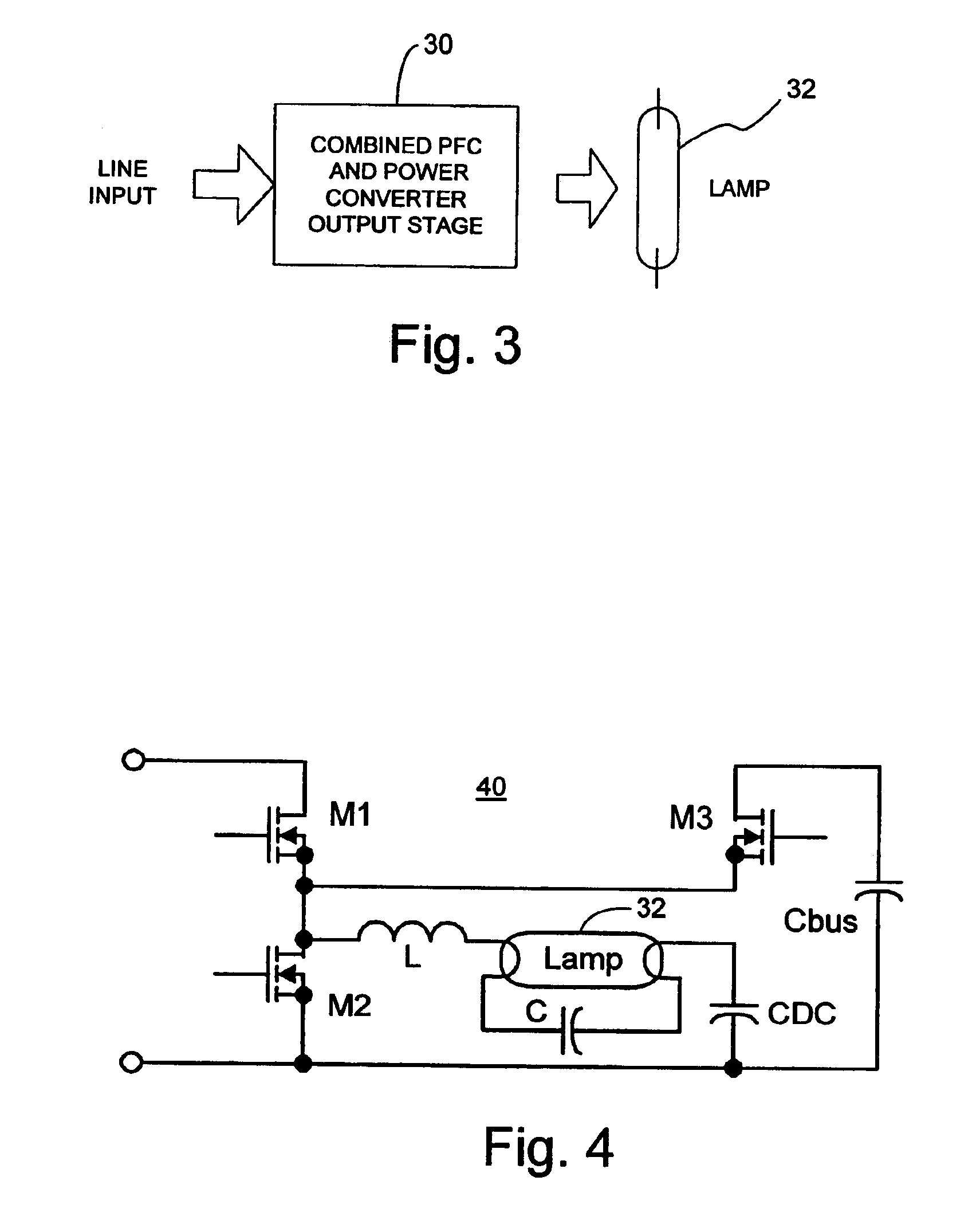
[0025]Referring now to FIG. 3, a block diagram of the single stage power converter with power factor correction (PFC) is illustrated as block 30. The single stage power converter is illustrated as driving a load, such as a resonant load for an electronic lamp ballast that powers a fluorescent lamp 32.

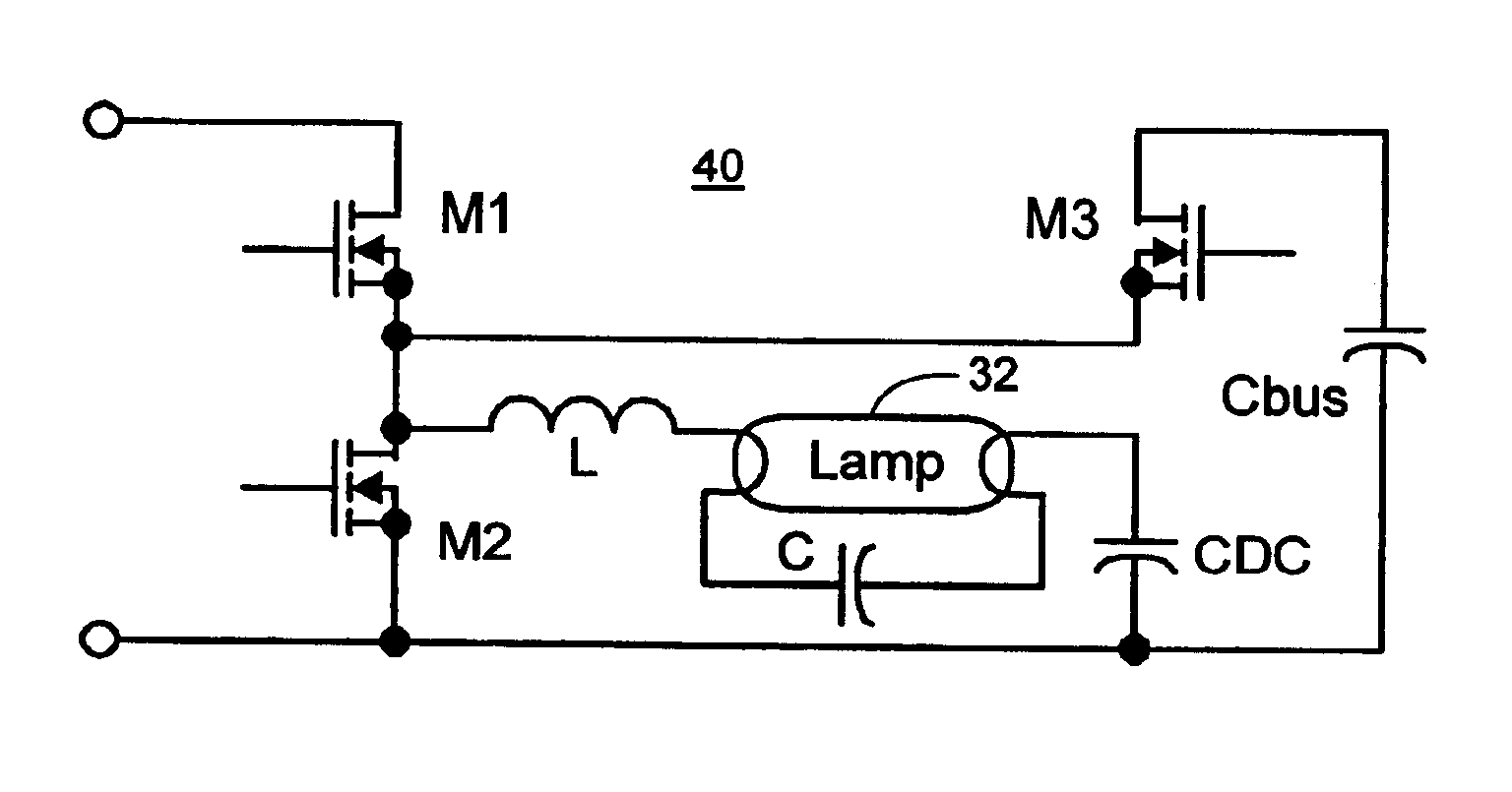
[0026]Referring now to FIG. 4, the circuit diagram of the single stage power converter according to the present invention is illustrated generally as circuit 40. Circuit 40 includes a switching half-bridge composed of switches M1 and M2, which is connected to a simple RCL ballast resonant output stage composed of inductor L, capacitor C, DC capacitor CDC and lamp 32. Switches M1 and M2 are operated in complementary fashion, that is, both switches are not on at the same time. In addition, when switches M1 and M2 are turned on and off in sequence, a dead time is introduced in between the switching sequence to avoid short circuit conditions. An exemplary dead time is approximately two micr...


PUM


Abstract

A power converter provides constant load power while achieving a high power factor in a single stage configuration with reduced component count and ratings. The power converter takes a rectified line input to a switching half-bridge that supplies current to a load. A series combination of shunt switch and capacitor is connected across the load to store energy from the input and supply energy to the load. The switches are operated with conduction angles that achieve constant power supplied to the load while drawing a sinusoidal current in phase with the input voltage to achieve high power factor. The circuit provides a simplified configuration over prior power converters that may be used with a resonant load as part of an electronic ballast or an AC-to-DC converter. The power converter configuration and operation also achieves a low total harmonic distortion on the input line power.

Description

CROSS-REFERENCE TO RELATED APPLICATION[0001]The present application is based on and claims benefit of U.S. Provisional Application No. 60 / 450,572 filed Feb. 27, 2003, entitled NEW SINGLE-STAGE PFC AND BALLAST CONTROL CIRCUIT / GENERAL PURPOSE CONVERTER, to which a claim of priority is hereby made and which is hereby incorporated by reference into the present application in its entirety.BACKGROUND OF THE INVENTION[0002]1. Field of the Invention[0003]The present invention relates generally to power converters and ballast controls with power factor correction (PFC), and relates more specifically to a single-stage power converter or ballast control that incorporates a PFC circuit.[0004]2. Description of Related Art[0005]Electronic ballasts and power converters that include a power factor correction (PFC) circuit are well known in the relevant industries. Typically, any type of general power converter, which includes electronic ballasts, have connected to their input a PFC circuit to prefe...

Claims


Application Information

Patent Timeline
IPC IPC(8): H02M1/00H05B41/282H05B41/28H02M1/42
CPCH02M1/425H05B41/28H05B41/282Y02B20/183Y02B70/126Y02B20/00Y02B70/10H02M3/335
Inventor THIERY, VINCENTNADD, BRUNO CHARLESRIBARICH, THOMAS J.RIBARICH, JOHN
Owner INFINEON TECH AMERICAS
Why Eureka
Try Eureka