Developing device conveying toner using a traveling-wave electric field and image forming apparatus using same

a technology of electric field and developing device, which is applied in the direction of electrographic process apparatus, instruments, optics, etc., can solve the problem of reducing the collision energy of landing the developer

Inactive Publication Date: 2005-08-23
SHARP KK
View PDF18 Cites 31 Cited by
  • Summary
  • Abstract
  • Description
  • Claims
  • Application Information

AI Technical Summary

Benefits of technology

[0013]With this specific feature, the width Lt of the developer existing area on the supplying member (the width Lt is orthogonal to the arranging direction of the respective electrodes) is smaller than the effective electrode width Le of the respective electrodes in their width direction (orthogonal to their arranging direction). This prevents the developer from entering the wiring pattern areas outside of the electrodes in their width direction, thereby surely preventing the scattering and the sticking of the developer in the areas.
[0015]With this specific feature, since the developer is conveyed in the same direction (“with” direction) with respect to the direction of moving the image carrying body that moves the electrostatic latent image in the circumferential direction, the moving speed of the developer in the developing area that faces the image carrying body becomes relatively slow with respect to the moving speed of the image carrying body. This decreases the collision energy for landing the developer on the image carrying body. Thus, even when the developer lands at the portion on the image carrying body where the developer has already existed, the scattering of the developer does not occur. This eliminates the adverse effect on the image, thereby forming a stable image.
[0016]Further, when the applied voltage applied to the respective electrodes is increased for increasing an amount of the developer conveyed on the developer conveying member and for reducing the occurrence of the sticking of the developer, the developer may be conveyed in the “with” direction with respect to the direction of moving the image carrying body. With this arrangement, in spite of the fact that the increased applied voltage applied to the respective electrodes increases the speed of conveying the developer, the moving speed of the developer in the developing area becomes relatively slow with respect to the moving speed of the image carrying body. This enables the developer to land softly on the image carrying body so as to prevent the scattering of the developer, thereby forming a stable image.

Problems solved by technology

This decreases the collision energy for landing the developer on the image carrying body.

Method used


Image

  • Developing device conveying toner using a traveling-wave electric field and image forming apparatus using same
  • Developing device conveying toner using a traveling-wave electric field and image forming apparatus using same
  • Developing device conveying toner using a traveling-wave electric field and image forming apparatus using same

Examples


embodiment 1

[Embodiment 1]

[0039]The following will explain an embodiment of the present invention.

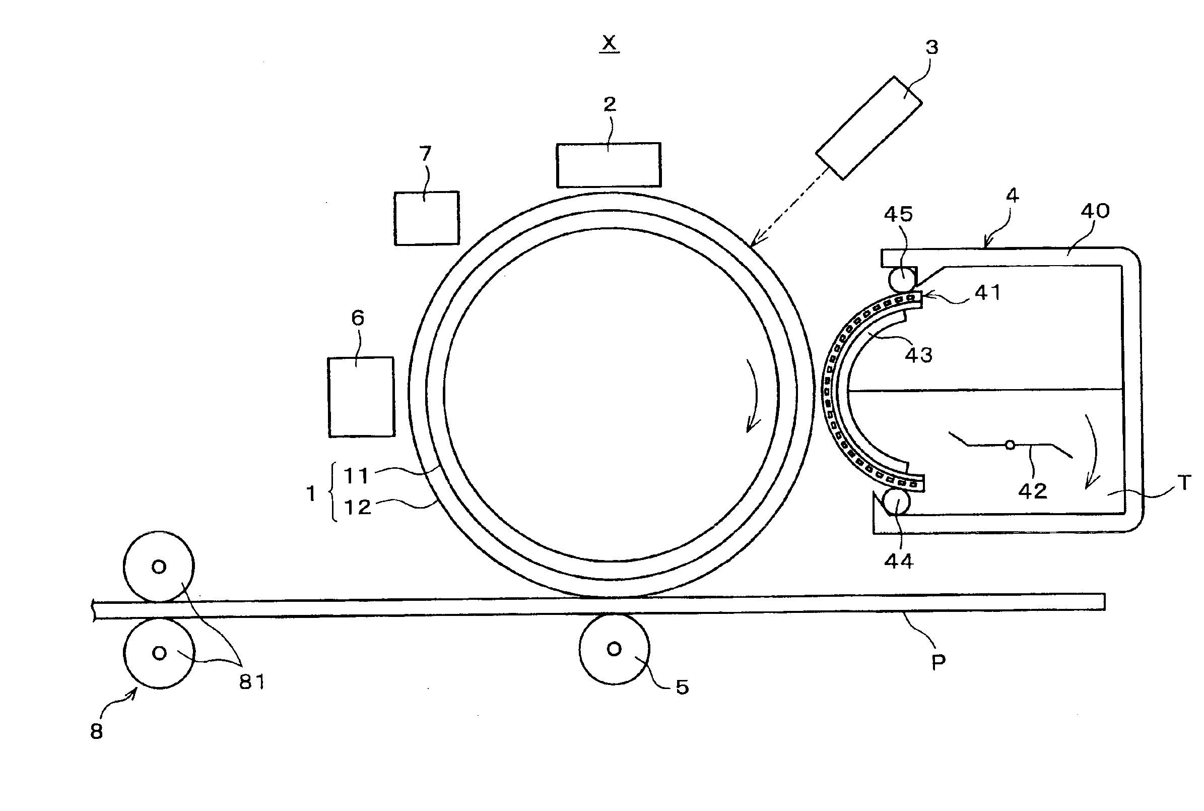
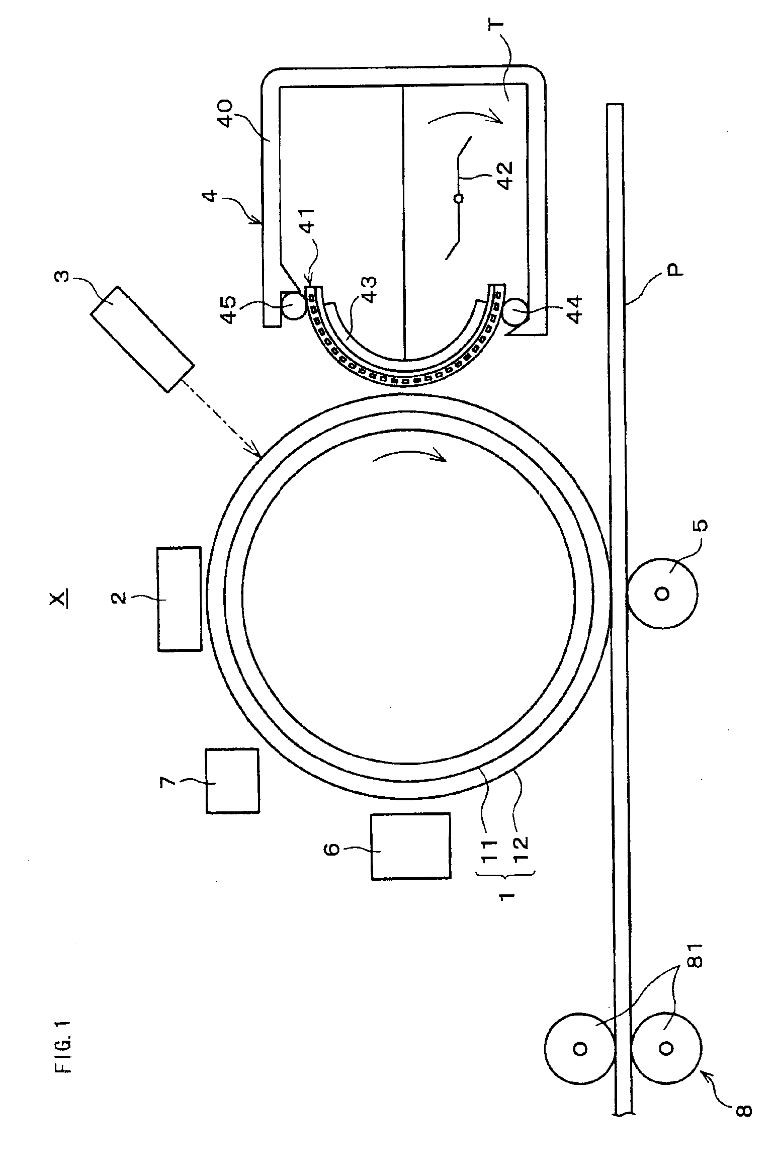
[0040]FIG. 1 shows an image forming apparatus adapting a developing device in accordance with Embodiment 1 of the present invention. Inside the image forming apparatus X, a cylindrical photosensitive drum 1 is provided as an image carrying body. Around the photosensitive drum 1 at the center, an electrically charging member 2, an exposing member 3, a developing device 4, a transfer member 5, a cleaning member 6, and an electrically discharging member 7 are sequentially arranged. Further, a paper conveyance route for conveying paper P is provided between the photosensitive drum 1 and the transfer member 5. On a downstream side of the photosensitive drum 1 with respect to a conveying direction of the paper conveyance route, a fixing device 8 having a pair of upper and lower fixing rollers 81 is provided.

[0041]In an electrophotography process, an image is formed in a following manner. An electrostatic...

embodiment 2

[Embodiment 2]

[0073]The following will explain another embodiment of the present invention.

[0074]In Embodiment 2, the developing device is provided with an endless belt which is driven at a very slow speed on the toner conveying member in the direction of conveying the toner. Note that, since the structure members other than the endless belt are the same as those of Embodiment 1, identical numbers with those used in Embodiment 1 are assigned, thus their explanation is omitted here.

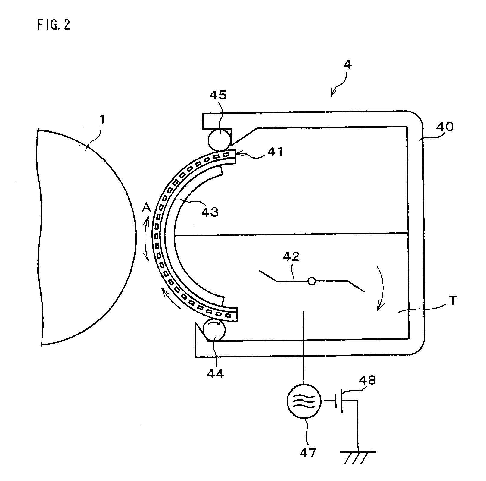
[0075]Namely, in Embodiment 2, as shown in FIG. 7, an endless belt 9 is provided on the surface (counter surface to the photosensitive drum 1) of the toner conveying member 41 so as to cover the surface of the toner conveying member 41 in a circumferential direction. The endless belt 9 is driven at a predetermined peripheral speed by a driving roller 91 that is provided in the casing 40 of the developing device 4.

[0076]As described above, by driving the endless belt 9 at the predetermined peripheral speed,...

embodiment 3

[Embodiment 3]

[0112]The following will explain a further embodiment of the present invention. Note that, an image forming apparatus in accordance with the present embodiment is the same as the image forming apparatus of Embodiment 1 except the direction of rotating the photosensitive drum 1 and the direction of conveying the toner by the toner conveying member 41. Since the structure members for composing the image forming apparatus are the same as those of Embodiment 1, identical numbers with those used in Embodiment 1 are assigned, thus their explanation is omitted here.

[0113]Namely, in FIGS. 10 and 11, the photosensitive drum 1 rotates in a direction of the arrow K. The toner conveying member 41 that faces the photosensitive drum 1 conveys the toner T in a direction of the arrow H so as to be the same as the direction of rotating the photosensitive drum 1.

[0114]Here, the following will explain the details of the operation of the toner conveying member 41.

[0115]The toner conveying...


PUM


Abstract

A developing device is provided with a developer conveying member in which a plurality of electrodes arranged on a substrate at a predetermined interval are coated with a surface protection layer, the developer conveying member being provided in a developing area that faces an image carrying body whose surface carries an electrostatic latent image, wherein developer is conveyed on the developer conveying member using a traveling-wave electric field that is formed by applying a polyphase voltage to the respective electrodes. The developing device is further provided with a supplying member for supplying the developer onto the developer conveying member, wherein (i) an effective electrode width Le of the respective electrodes in their width direction orthogonal to their arranging direction and (ii) a width Lt of a developer existing area on the supplying member, the width Lt being orthogonal to a direction of supplying the developer, are set so as to satisfy a relation of Lt<Le. This prevents the developer from entering wiring pattern areas outside of the electrodes on the developer conveying member, thereby surely preventing the scattering and the sticking of the developer in the areas.

Description

TECHNICAL FIELD[0001]The present invention relates to a developing device for developing an electrostatic latent image that is formed on a latent image carrying body (image carrying body) using developer, etc., and an image forming apparatus adapting the same; and in particular relates to a developing device employing a mechanism for conveying the developer using a traveling-wave electric field (electric field curtain), and an image forming apparatus adapting the same.BACKGROUND ART[0002]As a developing device adapted in an image forming apparatus using an electrophotgraphy process, such as a copying machine, a printer, and a facsimile machine, a developing device of a noncontact method, in which the development is performed without contacting a developer carrying body with an image carrying body, has come to receive attention. Suggested therein are methods using a powder cloud method, a jumping method, and a method using an electric field curtain (traveling-wave electric field).[00...

Claims


Application Information

Patent Timeline
Patent Type & Authority Patents(United States)
IPC IPC(8): G03G15/08
CPCG03G15/08G03G15/0803G03G2215/0651
Inventor SAKUMA, MASAMITSUADACHI, KATSUMIKAMIMURA, TAISUKETOIZUMI, KIYOSHIGOTOH, TOSHIMITSU
Owner SHARP KK
Why Eureka
Try Eureka