
Digital pressurization compound terminal

a technology of compound terminals and digital pressure, which is applied in the direction of functional valve types, operating means/releasing devices of valves, container discharging methods, etc., can solve the problems of limited to a maximum pressure of 30 bar, conventional pressurization equipment can only convey gas, and the surplus gas is always expelled outside, so as to facilitate filling, pressurization, and purge operations. the effect of user convenien

Inactive Publication Date: 2005-08-30
FERNANDEZ MANUEL ROLAND
View PDF10 Cites 3 Cited by
  • Summary
  • Abstract
  • Description
  • Claims
  • Application Information

AI Technical Summary

Benefits of technology

[0014]It is an additional object of the instant invention to provide pressurization equipment that is durable and highly accurate.
[0017]The digital pressurization compound terminal is hand held and ergonomically designed equipment, comprising a main body made in a high-resistance alloy and a high-accuracy digital pressure gauge sheltered in a thick anti-shock silicone shell. The digital pressurization compound terminal has a purge system which allows the fluids or the emulsified gas to be easily released and properly collected in a drain container. With the design of the digital pressurization compound terminal, the filling, pressurization, and purge operations are made easier, cleaner and faster for the user. In addition, a filtering cartridge is installed in the digital pressurization compound terminal's main body interior system to filter the fluid so it is not polluted before penetrating the system being maintained.

Problems solved by technology

In addition, they are limited to a maximum pressure of 30 BAR.
Moreover, conventional pressurization equipment can only convey gas, and surplus gas is always expelled outside.
Existing pressurization equipment, as noted above, is cumbersome.
Therefore, when the user is moving the unit around, the non-rotating connections get loose, often provoking leaks.
This results in the pressure indications becoming distorted, forcing the user to tighten all the connections again, before resuming the task.
There are no known devices in the prior art that address the shortcomings in the prior art in a single unit.
In addition, multiple pieces of equipment are required for fluid filling, purging and pressurizing operations and are limited in pressure capacity.

Method used


Image

  • Digital pressurization compound terminal
  • Digital pressurization compound terminal
  • Digital pressurization compound terminal

Examples


Embodiment Construction

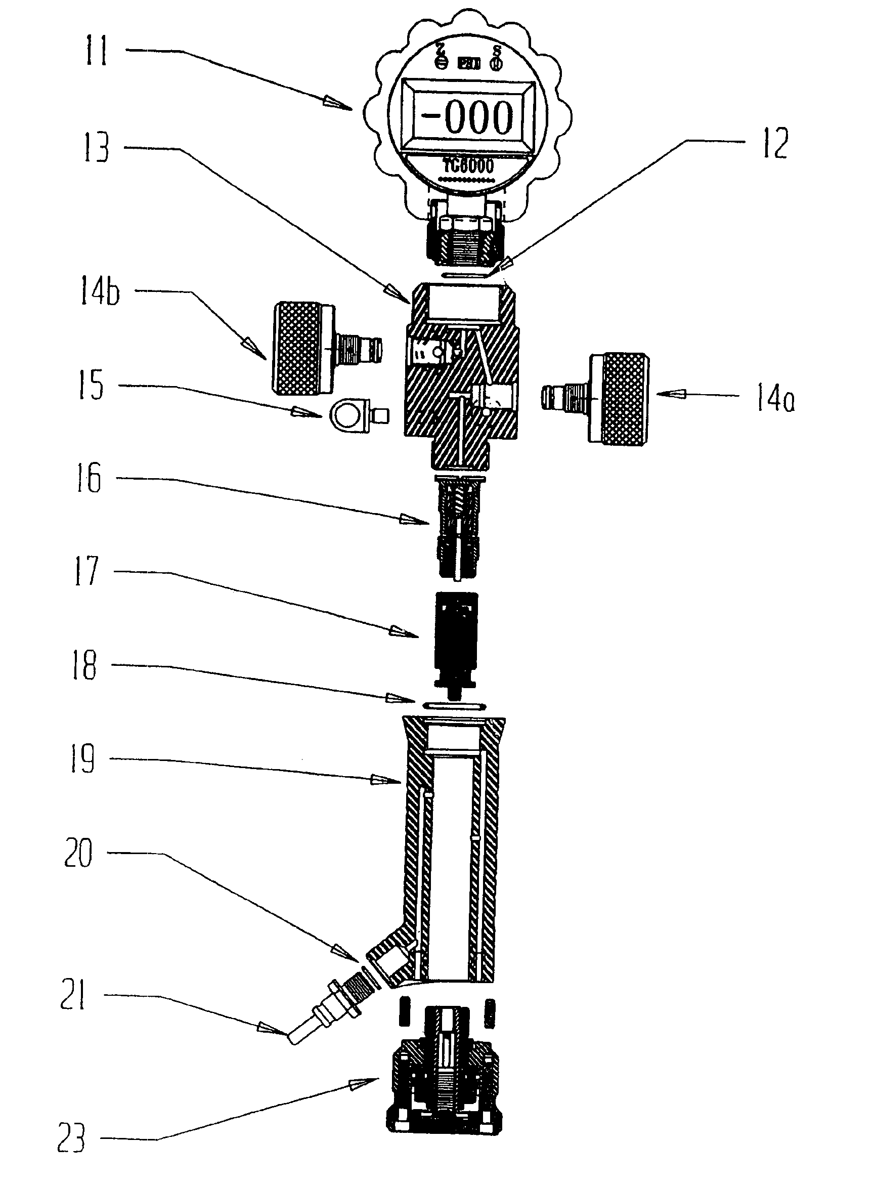
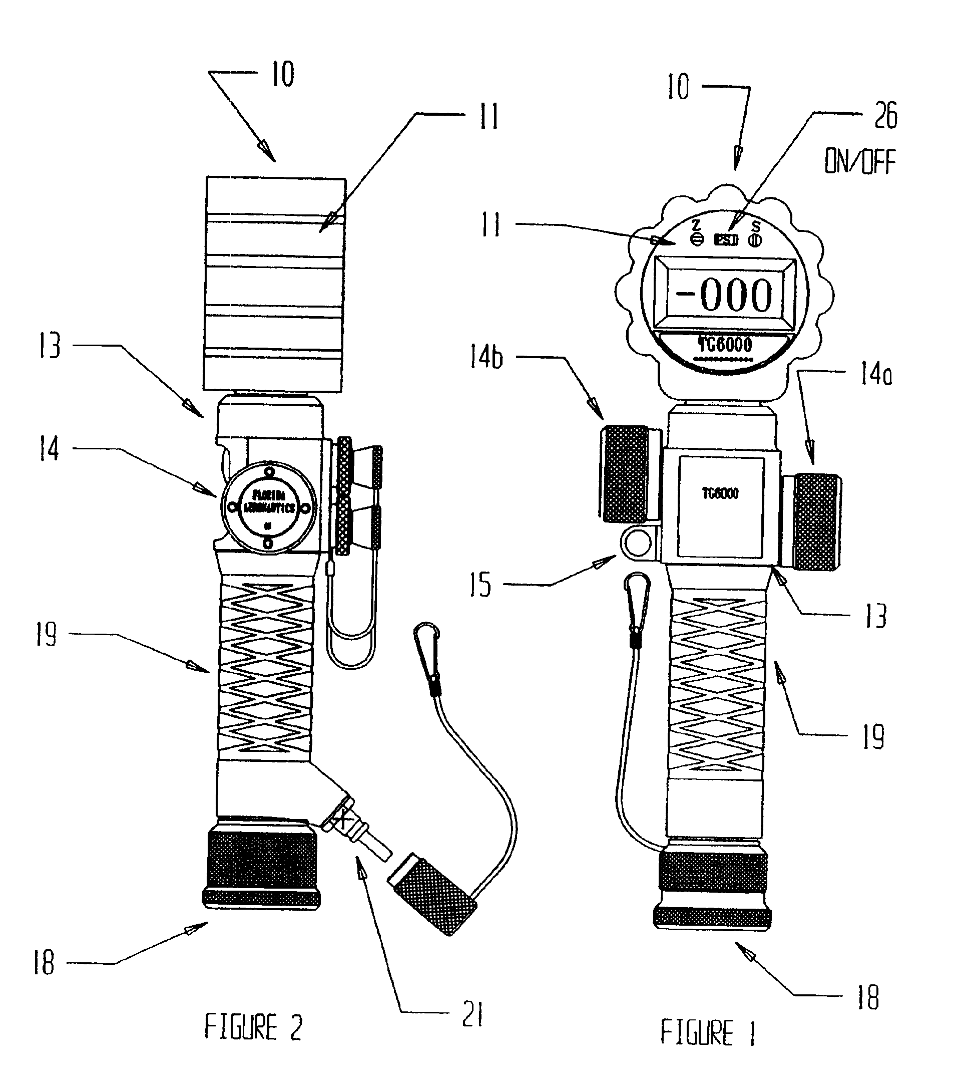
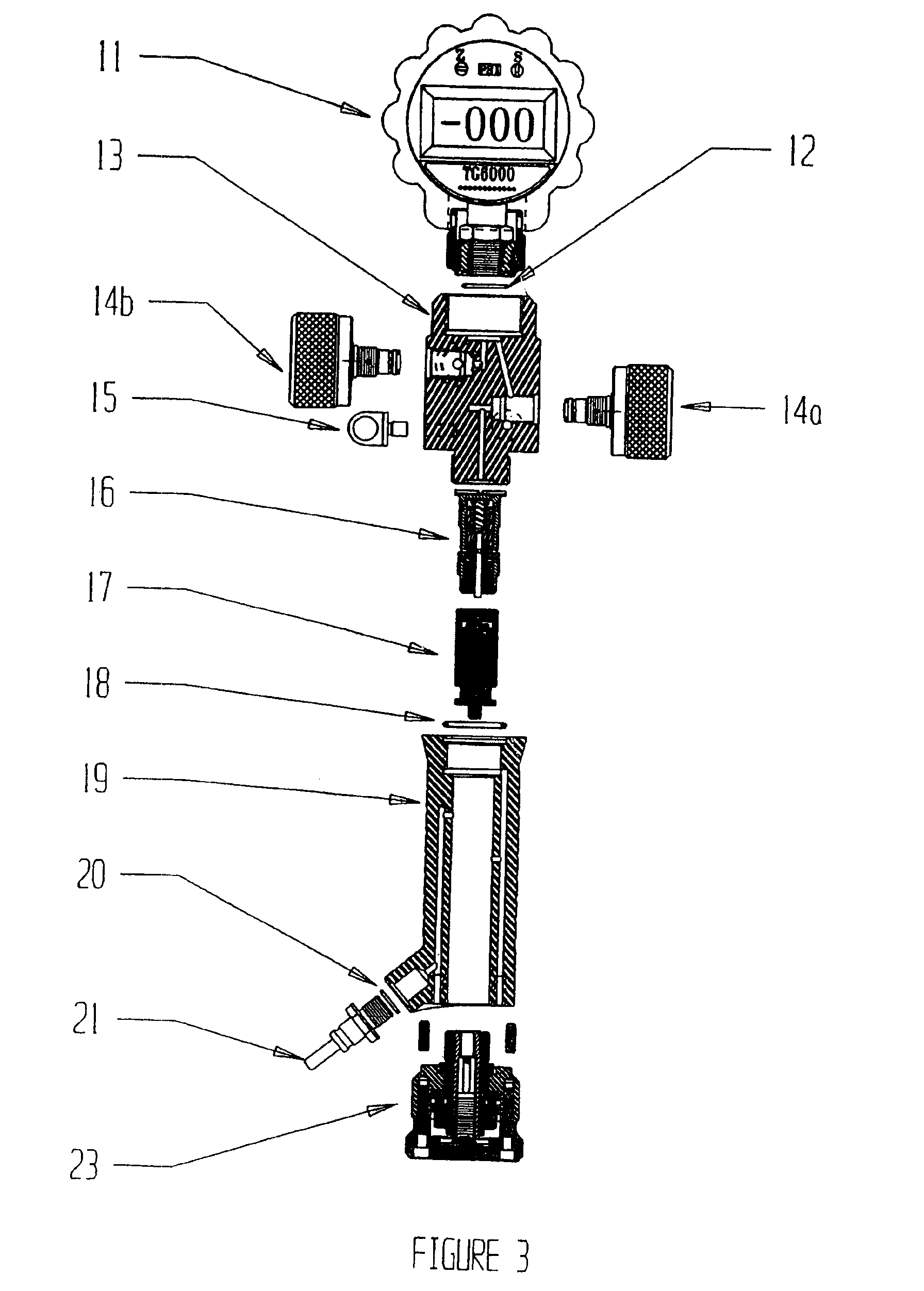
[0022]With reference to the drawings, FIGS. 1-3 depict the preferred and alternative embodiments of the instant invention which is generally referenced as a digital pressurization compound terminal and, or by reference numeral 10. Referring to FIG. 1, the instant invention 10 comprises a digital pressurization compound terminal 10 made in one piece and preferably has overall dimensions of 290 mm long, 87 mm wide and 74 mm thick. These dimensions may vary provided performance is not jeopardized. The digital pressurization compound terminal 10 is compact and has an ergonomically designed handle 19 that facilitates convenient holding and handling. The instant invention 10 may also include a carrying case having foam compartments for securing and protecting the device 10. The digital pressurization compound terminal 10 regulates pressure, has a negative and positive pressure range from −15 PSI to 6300 PSI, can be used with Nitrogen gas and has a control valve 14 to complete a pressuriza...


PUM


Abstract

A digital pressurization compound terminal 10 comprising a high accuracy digital pressure gauge 11 sheltered in a silicon housing, main body 13 made of a high-resistance allow and dimensioned to be held in the palm of the user's hand, o-ring 12, control or HP valves 14, ring 15, regulator assembly valve 16, equipped piston 17, second o-ring 18, inferior body and handle 19, third o-ring 20, male quick coupling 21, screw 22, regulator setting wheel 23, purging female quick coupling 24, service female quik coupling 25 and on-off switch 26.

Description

CROSS REFERENCE TO RELATED APPLICATIONS[0001]This application claims the benefit of Provisional Application Ser. No. 60 / 296,265 filed Jun. 6, 2001.STATEMENT REGARDING FEDERALLY SPONSORED RESEARCH OR DEVELOPMENT[0002]N / ACOPYRIGHT NOTICE[0003]A portion of the disclosure of this patent document contains material that is subject to copyright protection. The copyright owner has no objection to the facsimile reproduction by anyone of the patent document or patent disclosure as it appears in the Patent and Trademark Office patent file or records, but otherwise reserves all copyrights rights whatsoever.BACKGROUND OF THE INVENTION[0004]1. Field of the Invention[0005]This invention relates generally to pressurization equipment, and more particularly, to a digital pressurization compound terminal for filling, purging and pressurizing fluids, such as hydraulic fluid, in aircraft, helicopter, automobile, military, agricultural, space and marine industries.[0006]2. Description of the Background A...

Claims


Application Information

Patent Timeline
IPC IPC(8): F17C13/04
CPCF17C13/04Y10T137/6123Y10T137/8326Y10T137/7808Y10T137/87169Y10T137/3677
Inventor FERNANDEZ, MANUEL ROLAND
Owner FERNANDEZ MANUEL ROLAND
Learn More