Torsion beam suspension

a technology of rotating beams and suspension arms, which is applied in the direction of suspension arms, pivoted suspension arms, axle units, etc., can solve the problems of deteriorating welding properties, warping of the mounting surface of the spindle support plate, and increasing weigh

Inactive Publication Date: 2005-08-30
F TECH INC
View PDF7 Cites 16 Cited by
  • Summary
  • Abstract
  • Description
  • Claims
  • Application Information

AI Technical Summary

Problems solved by technology

However, the above-mentioned conventional design has a problem in that the spindle axle line and the trailing arm major cross-section are largely offset with the angular U-shaped bracket disposed therebetween, so that the bracket must have a wall thick enough to reliably support a load from the wheel, resulting in an increased weight.
However, in reality, when the trailing arm end is welded to the spindle support plate, the spindle mounting surface of the spindle support plate may be warped by the heat of welding.
In order to prevent this thermal warping, it is necessary to make the spindle support plate sufficiently thick (for instance, over 10 mm), so that the total thickness of the spindle support plate and the mounting flange (for instance, 10 mm thick) integral with the spindle which is connected to the spindle support plate, becomes over 20 mm, disadvantageously resulting in no reduction in weight.
Moreover, there is also a problem that welding property is deteriorated due to a large difference in thickness of the trailing arm having a small wall thickness and the spindle support plate having a large wall thickness.
However, in this case, because the spindle axle line is the reference for the surface cut, it is necessary to rotate the whole trailing arm in conducting the surface cut, so that machining becomes very complicated and costly.
Therefore, a weight increase is unavoidable.

Method used


Image

  • Torsion beam suspension
  • Torsion beam suspension
  • Torsion beam suspension

Examples


Embodiment Construction

[0023]The present invention will be described with reference to a preferred embodiment shown in the attached drawings.

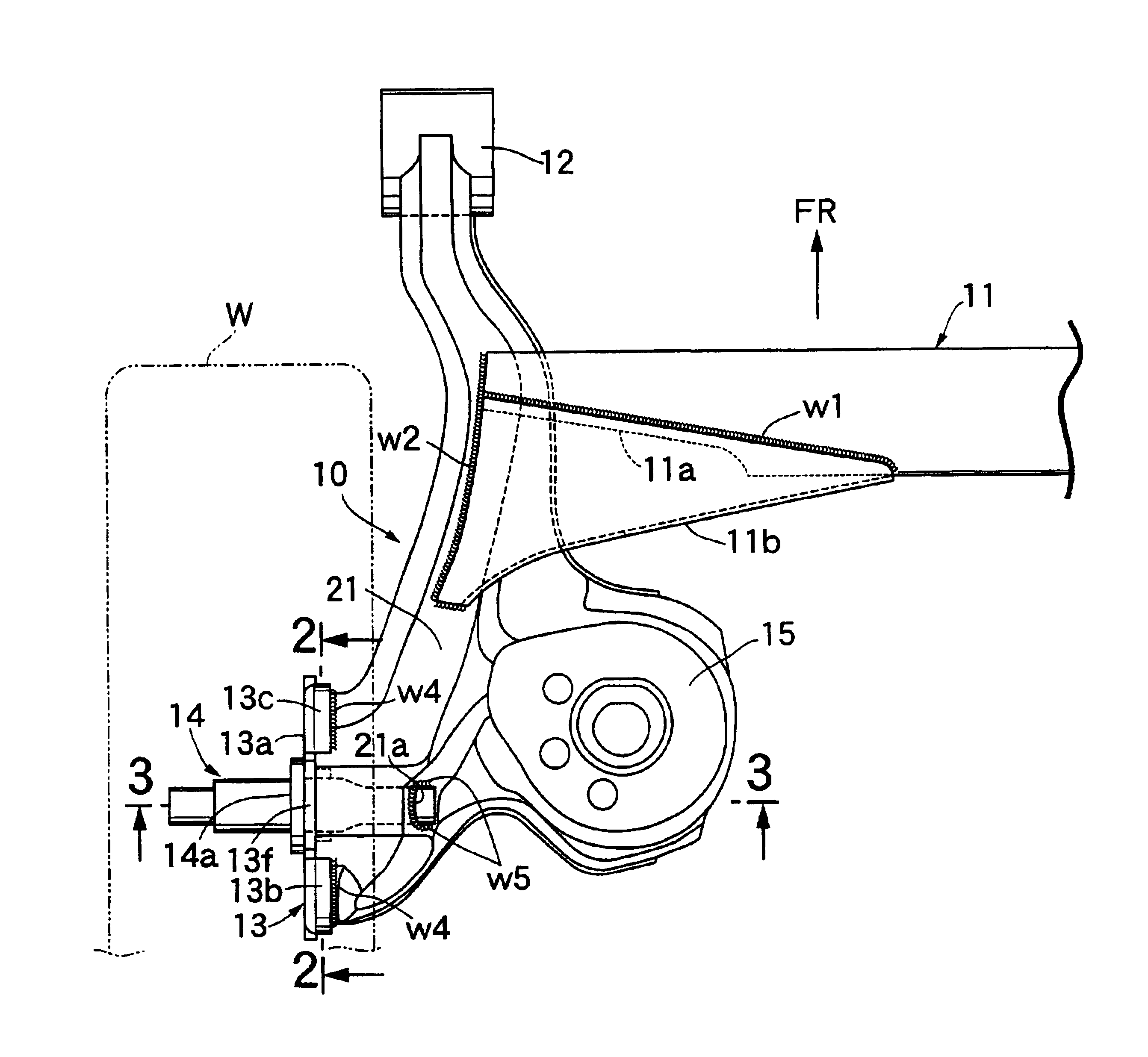
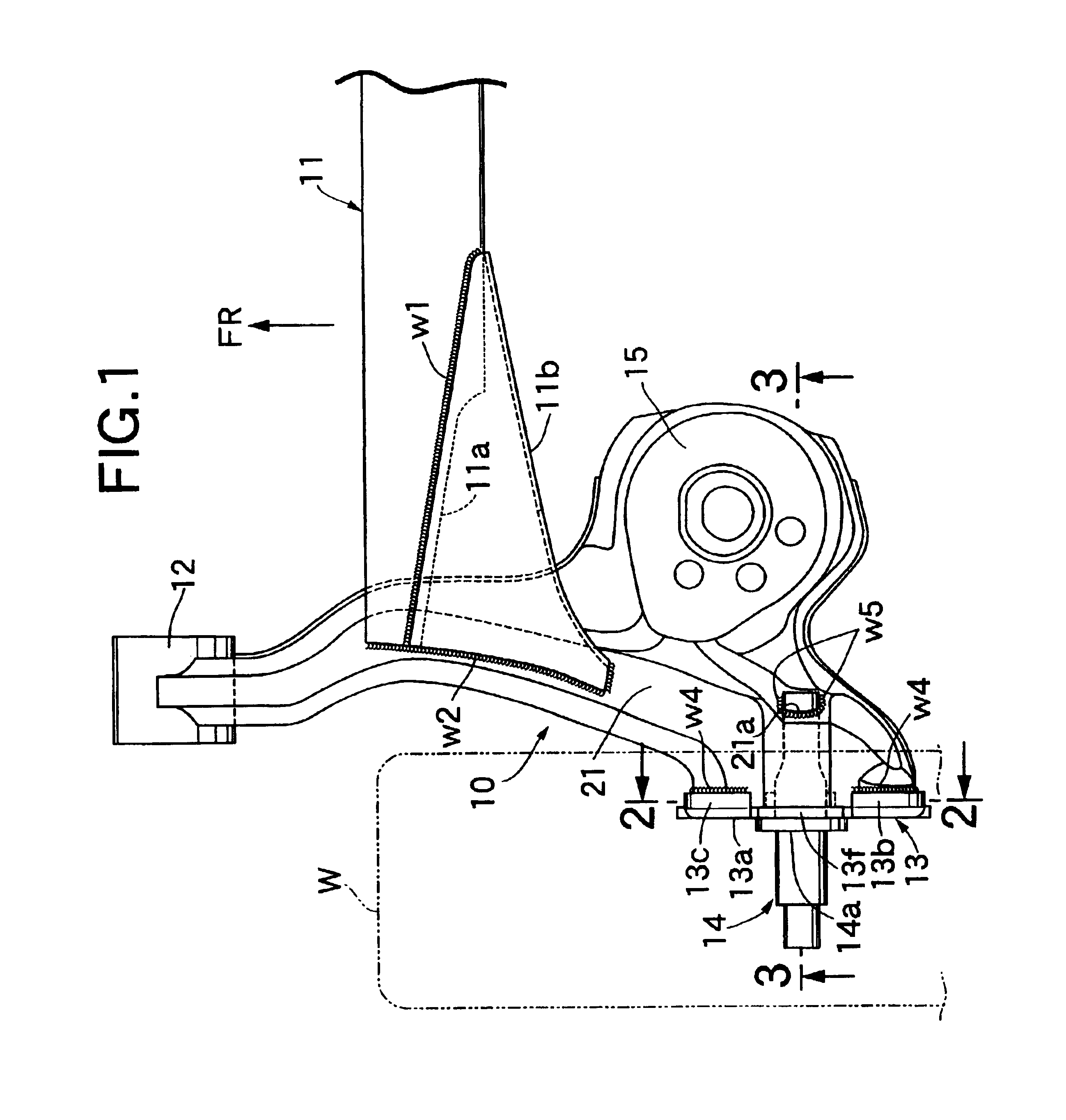
[0024]FIG. 1 is a front plan view of the left half of a torsion beam suspension for rear wheels of an automobile, and the right half of the torsion beam suspension has a construction symmetrical with that of left half with respect to the longitudinal centerline of the vehicle. The torsion beam suspension has left and right trailing arms 10, 10 which extend in the longitudinal direction of a vehicle body, and torsion beam 11 which extends in the lateral direction of the vehicle body to link to the left and right trailing aims 10, 10. The front end of the trailing arm 10 is welded to a tubular trailing arm support 12. The trailing arm 10 is vertically pivolably supported on the vehicle body via a rubber bushing joint (not shown) accommodated in the trailing arm support 12. A rear wheel W is rotatably supported on the spindle 14 fixed to the spindle support plate 13 whi...


PUM


Abstract

Opposite ends of a torsion beam are connected to left and right trailing arms, and a spindle which supports a wheel is secured to a spindle support plate which is welded to each of the left and right trailing arms. Bent flanges which are formed in the outer periphery of a body of the spindle support plate, are fitted to the outer periphery of the end of trailing arm and secured by welding. With this arrangement, thermal warp of the body of the spindle support plate which supports spindle can be prevented, and not only can the mounting precision of the spindle be improved, but also the thickness of the spindle support plate can be reduced to reduce the weight.

Description

BACKGROUND OF THE INVENTION[0001]1. Field of the Invention[0002]The present invention relates to a torsion beam suspension comprising: vertically pivotable left and right trailing arms extending in a longitudinal direction of a vehicle body; a torsion beam extending in a lateral direction of the vehicle body, the opposite ends of which are connected to the left and right trailing arms; a spindle support plate welded to each of the left and right trailing arms; and a spindle fixed to the spindle support plate so as to axially support a wheel.[0003]2. Description of the Related Art[0004]A conventional torsion beam suspension is known from Japanese Patent Application Laid-open No. 2000-94917.[0005]In the conventional torsion beam suspension, a trailing arm is a hollow member made by combining and integrally welding press-formed upper and lower plates, and a bracket formed from an angular U-shaped metal plate is welded to the trailing arm to secure a spindle support plate which supports...

Claims


Application Information

Patent Timeline
Patent Type & Authority Patents(United States)
IPC IPC(8): B60G3/00B60G21/00B60G21/05B60G3/14B60G7/00B60G9/04
CPCB60G3/145B60G7/008B60G21/051B60G2200/21B60G2200/42B60G2202/136B60G2204/1246B60G2204/148B60G2206/012B60G2206/20B60G2206/30B60G2206/50B60G2206/722B60G2206/8102B60G2206/8201
Inventor INOUE, MITSURUHORIUCHI, KIYOSHI
Owner F TECH INC
Why Eureka
Try Eureka